During the 90s a wealth of research was developed and experience gained. However much of this validation seems to have been disregarded, somewhere down the line, and many within the building industry still regard computational fluid dynamics (cfd) as a toy.
Perhaps we haven't advanced very far over the past decade in terms of understanding what cfd is all about. The image portrayed by people within the construction industry regarding the use and so-called understanding of modelling still suggests that cfd is in its infancy.
Too often we hear comments like: "CFD is well established in certain fields but in this instance may not be the appropriate tool to use." Within the building industry, cfd is not given the respect it deserves and is generally undersold.
The modeller
CFD is only as good as the person driving it. Perhaps it is the lack of experienced modelling expertise within the building industry that leads to this bad press. The use of cfd is generally carried out by the modeller. This is not to be confused with a button pusher. A six year old can be led through the motions of creating a cfd model but, if the understanding of the problem is not present, the results will be unsatisfactory.
To get meaningful results from cfd, the modeller must have a good understanding of the problem to be modelled.
While it is not feasible to understand everything, it is necessary to have a good grasp of the physics of the particular engineering problem and to capture the physics to the appropriate level of detail to make an informed engineering analysis.
Mathematically it is possible to achieve a numerical solution that is correct, and a mathematician might be minded to sign off the results at this point. A physicist, alert to the limitations of the model itself for example its lack of an advanced turbulence model, may consider the solution as still unreliable.
Then there is the young graduate who has enthusiastically jumped to the controls of a cfd package, without knowing too much about it or being able critically to appraise its output.
Finally, you have the engineer who just wants an image and who is quite happy to accept anything that coincides with his line of thought – blind to the prospect of spending six months re-engineering a failed design.
Blaming the tools
Often people blame the computer codes they drive as being deficient. However this is not true of all cfd codes. The real problem is often that the code cannot provide the modeller with the capabilities needed to model the physics or the usability to provide commercial turnaround times. Some responsibility must lie with the driver of the code, regardless of what the sales rep told them.
The biggest abuse of modelling can be attributed to a lack of engineering experience. A raw graduate has not yet acquired the experience necessary, (but may have very good computer skills). The time served engineer will have the experience but may not be able to drive these codes quickly.
So cfd is only as good as the person driving it. Even then it is still subject to the following:
- the user's interpretation of the problem;
- the level of physics required;
- the physical boundary conditions;
- the geometric detail required;
- the quality of the numerical model produced;
- the type of analysis – steady or transient modelling;
- most importantly, the interpretation of the results.
Extensive research and commercial work has been undertaken using cfd for external airflows around buildings over the past two decades. A quick internet search reveals numerous European funded projects that have been completed, (interestingly, most of the academic work has been carried out in Scandinavian countries). This is not to mention the wealth of papers available worldwide.
The use of cfd in the building industry has become routine on most building projects. With informed and correct use, cfd can be an invaluable tool which provides insight into complex flow phenomena.
A word of warning
CFD should not be used to tell us what we want to hear or suppress scenarios that represent what may happen on the basis of a cost saving.
In our early cfd work at Hoare Lea, we were fortunate to have a client who set us some challenging ventilation and air contaminant capture analyses. In some instances the results initially surprised us – but, almost invariably, closer scrutiny tended to justify the model's outcome rather than our preconceptions. It was an important step in understanding the power of cfd as a design aid and in using it as an early testing system.
The following are some examples of cfd which demonstrate its progress from infancy towards maturity.
Wind engineering
The use of cfd to model the impact of external winds is, according to some, limited by its inability to model the transient effects. As with all modelling, whether physical or computational, it is only as good as the model construction. Traditionally, wind effects are scale-modelled in wind tunnels which, once set up, allow for different wind aspects, velocities etc to be quickly evaluated. It could be argued that scaled down mock-ups in wind tunnels can fail to capture all the physics. For example they tend to be isothermal and unable to deal with modelling where air temperature/buoyancy is used as part of the overall driving pressure regime. It is possible to run cfd models with more detail than a wind tunnel would allow. The issue of capturing the physics is of course down to the boundary layer capture, thermal effects, radiation and turbulence model. Some examples of external transient cfd models and some internal and external calculations coupled into one single simulation follow.
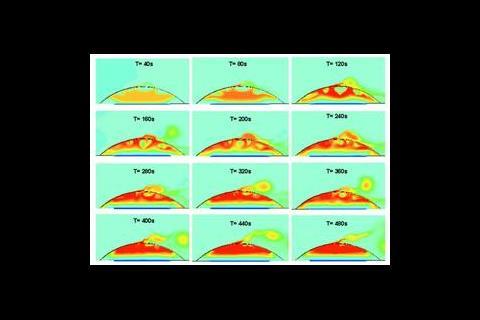
Figure 1 shows snapshots from a transient run, illustrating the power of cfd in cases that combine wind and thermosyphon pressure effects.
The concept building is naturally ventilated with intakes at low level and a modicum of cooling applied through a ground coupled labyrinth. The external skin of the building is ventilated using a specially designed plenum to achieve optimal dissipation of solar gain and assist in ventilating the main building.
The model includes a pulsating wind with thermal effects. Use is made of the large eddy simulation turbulence model to capture the physics. Similarly the radiative transport equations coupled with the Navier Stokes and energy equations are used to model momentum and heat transfer mechanisms, (ie conduction, convection and radiation).
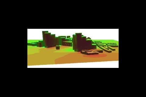
Figure 2 shows the use of cfd as an alternative to wind tunnel testing on a fairly complex but conventional study of urban wind effects. (The 3d model, once constructed, can also be used for other design information – solar shading and shadowing for example.) Displacement modelling
The modelling of displacement and low energy flow type simulations is contentious.
From personal experience it is of the utmost importance to model exactly what is in situ. The concept of low energy systems utilising thermal gradient buoyancy forces to ensure ventilation is commendable. However these systems, by their very nature, are susceptible to jetting effects, incorrect installation, problems regarding location of heat sources and control system to name a few. It is therefore essential to model to the correct level of detail. An accurate representation of the boundary conditions is required to provide a realistic representation of the ventilation system. Information provided by suppliers and manufacturers, may be correct under laboratory conditions but will vary according to its installation.
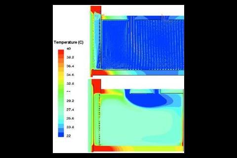
The modelling of grilles and components is paramount as the flow characteristics vary. Figure 3 shows a cfd model of a call centre equipped with a displacement ventilation system.
Solar radiation modelling The ability to model solar radiation in addition to surface to surface radiation is very important, particularly in the area of facade engineering. Part L2 of the Building Regulations means it will often become necessary to improve the U values of facades to achieve compliance.
Unfortunately it is not possible to replicate the impact of solar radiation in a physical mock-up., though not everyone will agree.
But it could be argued that using thermal mats to emulate solar effects does not give an accurate interpretation of the boundary layer and convection effects of the sun. The accuracy of a physical mock up depends very heavily on the arrangement of the thermal mats.
Their positions, areas and assigned surface temperatures would need to vary markedly, for example, between simulating well shaded normal glass and unshaded high performance glass – yet both may result is identical levels of solar heat admission.
The ability to model external convection, conduction through the walls, solar transmission, absorption of media and subsequent air flow and heat transfer is best realised through the use of cfd.
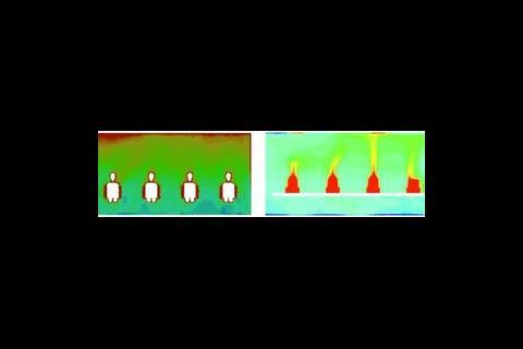
Figure 4 is a comparative example of two window configurations.
The model includes 0·5mm thickness for the coatings and all glass and wall thicknesses and their properties. The only heat gain source in the model is solar irradiation. The model also includes internal and external airflows and their convection effects, heat conduction and re-radiation.
Chilled beam modelling
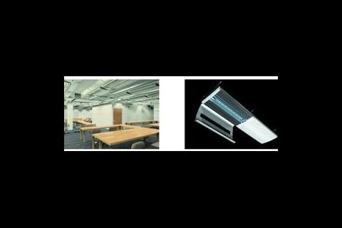
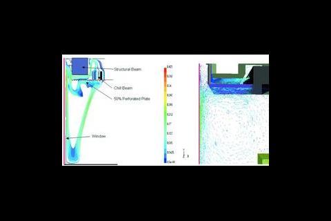
Figures 5a and 5b show the combined use of visualisation techniques and numerical modelling in prototyping. In this case, working with an architect on a bespoke chilled beam/luminaire assembly, both its appearance and thermal performance were modelled at a very early stage in the design process.
The use of low energy passive chill beams on perimeters is a great innovation. However the performance of a beam in such situations is very sensitive to its configuration relative to surrounding elements. Massive performance decrements can arise if it is used incorrectly.
Passive edge beams are designed to capture thermal plumes and deal with them as near as possible to the window.
If, for example, the buoyant thermal plume is confronted with blinds, louvres, down stands and the beam is located a metre away from the window, its performance will likely be drastically reduced.
CFD has been used to establish the performance of chilled beams prior to installation and physical mock-ups (see Figure 6).
By carrying out a cfd analysis to the correct level of detail, (that is with actual beam louvres, down stand and perforations), it is possible to optimise all of these criteria to achieve a feasible design.
Part L2
Using cfd in conjunction with in-house developed software Hoare Lea Virtual Engineering carry out extensive analysis of buildings to ensure Part L2 compliance can be achieved. While dynamic modelling can predict total energy consumption and carbon emissions, we believe that the best approach is to look at all the methods available to ensure the most innovative and commercially viable designs are explored.
The future
Modelling can be used to enable better, more informed, engineering solutions. The building industry is further down the modelling road than some people believe.
Modern engineers must be ready to use the latest advanced technology to achieve workable, innovative engineering and software solutions. Today's consulting engineering practice is now home not only to engineers but also computational and physical modellers, and software developers.
But like all new technology it must not be used for its own sake. Careful use of cfd can show engineers how to make their work better. But incorrect use can lead to more work and expense later. Computational fluid dynamics is certainly not a toy.
Source
Building Sustainable Design
Postscript
Paul Kingston is principal, Virtual Engineering, Hoare Lea Consulting Engineers. Tel 01454 201020 or alternatively visit www.hlve.co.uk








No comments yet