


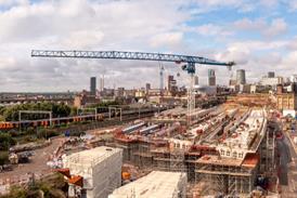


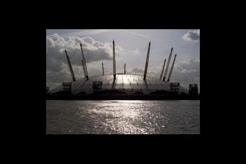
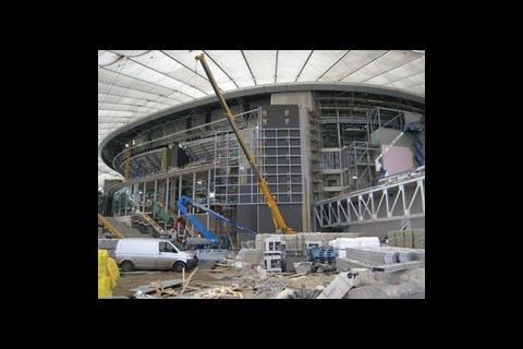
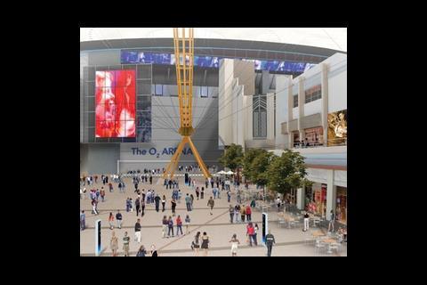
London’s new O2 Arena and its vast surrounding entertainment complex sit beneath the original tented structure of the Millennium Dome – which added extra complexity to the construction and design of services
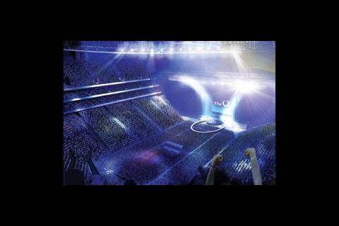
Only when you’re high up, standing on the access gantries looking down into the sweeping O2 Arena, does the scale of the project become truly apparent. Below, the hundreds of workers racing to get the venue completed for its inaugural event in July seem insignificant against the backdrop of raked seating and 10-storey high roof supports. Even the articulated lorries unloading insulation for the planned ice rink look tiny.
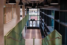
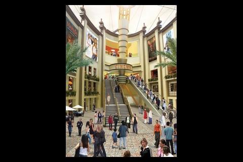
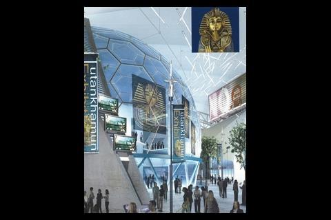
And yet, despite its size, this 23,000-seat venue under the cover of the Millennium Dome is only half of the story. Surrounding it is another equally impressive development – the “Entertainment district”. This is a strip of shops, restaurants, cinemas and clubs that stretches the same length and breadth as London’s Bond Street, and will also sit within the Dome. Together known as “The O2”, the arena and mall area inhabit a space equivalent to 13 Albert Halls, rising up to a height just shy of the 50 m tall fabric of the roof of the Dome. They fill every inch of the cavernous 320 m diameter space.
Building within the confines of the Dome structure put huge constraints on the design and construction process. The project was, says Jim McCarthy, director of consultant ME Building Services, a challenging brief. “It was a truly unique project. We’ve worked on other indoor arena projects in the US, including the Pepsi Center in Denver and the Staples Center in LA, but none of them have this building-within-a-building arrangement.”
Each of the interior structures has been created as an independent structure in its own right – not reliant on the tented Dome covering, still owned by government agency English Partnerships, that surrounds it. However, although the Dome does have an effect on the thermal performance of the interior environment, the space was treated as an external environment during the design stage, with a design criterion of -4°C used.
“The U-value of the tent is negligible, but it does have one and it also takes the wind away and shades against solar gains,” explains David Griffiths, ME Building Services’ mechanical engineer on the project. “A study showed a wintertime temperature of about 10°C inside, but the design doesn’t take that into account – instead, all the structures are treated as autonomous buildings in case the tent isn’t always there. In theory, though, we should see an increase in efficiency from the boilers and the cooling plant.”
ME Building Services worked closely with the arena’s architect HOK, the architect of the shopping and entertainment area RTKL, and structural engineer Buro Happold to come up with a solution that would work within the existing Dome. One of the initial hurdles was calculating just what the energy requirements would be. “Estimating the electrical load for the development was complicated because there were no benchmarks to refer to,” says McCarthy. “The main issue was that the indoor arena is at the centre of the Dome, which imposes increased fan power for fresh air delivery and exhaust systems.”
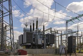
To calculate the electrical load, thermal models and computational fluid dynamics analysis of the arena were carried out for all modes of operation to establish highest potential consumption. Only when armed with this data could they set about convincing utility supplier EDF to bring the necessary 17 MVA onto site.
Energy needs
By far the biggest influence on the load profile is the energy needed to move fluids in and out of the Dome. Fresh air, LTHW, condenser water and toilet supply and extract all have to travel about 160 m from the perimeter, where the original 12 “service cylinders” are being refitted with plant. Achieving this requires supply air fans rated at 1,500 Pa and a massive pumping plant room, which sits beneath the service yard and pushes LTHW and chilled water around two main circuits. These feed both the arena and Entertainment district. “We believe this unique situation has imposed something like a 20% increase in energy demand,” adds Griffiths.
The arena is treated as a single-zone, constant volume all-air system. Two massive air intake ducts, one at ground level and another at mezzanine level, draw fresh air into four plant rooms, each kitted out with air handling units capable of delivering air at 56 m3/s. These units are ducted up to high level, where they feed into a massive distribution duct, 2 m in diameter, which then directs conditioned air down into the arena via a series of jet nozzles.
A constant volume system was the only solution, explains Griffiths. “You can’t do a variable volume system because the nozzles have such a long way to throw onto the occupants. If you start to change the pressure drop across the nozzles and the air volumes, the air distribution in the bowl falls apart.”
The use of CFD modelling ensured that conditions could be adapted to the different uses the arena undergoes simply by varying the supply air temperature and mix of fresh air and re-circulated air, which is controlled using CO2 sensors. The only major exception is when the arena’s ice hockey rink is in use. “In this mode, the ice pad has to have a volume of still air above it to help maintain its temperature,” says Griffiths. “So the delivery temperature of the air goes to 18°C, rather than the normal 21°C, and the nozzles that would usually throw air down onto occupants in that area motor away, so you don’t get air blowing across the pad and, instead, create a cocoon of still air.”
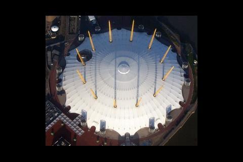
Stale air is extracted from the arena through roof fans into the void beneath the Dome’s tented roof. From here, it vents to the outside via a combination of the iris (the opening flaps and fans in the centre of the roof) and the mast fans. “The problem with the mast fans is they can only run at 60% speed because the noise at full speed is unbelievable,” says McCarthy. “They will purge at night when everyone has left but, primarily, they are for smoke extract.”
Raising the roof
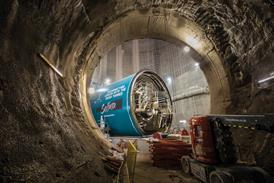
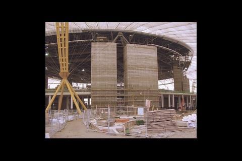
If all this sounds like a straightforward solution, constructing the systems called for some ingenuity. The main problem was that the Dome prevented the inner roof of the arena from being erected in a conventional way using cranes. To get around this, the eight concrete cores that would support the roof were cast in situ around the perimeter, resembling a “modern-day Stonehenge”.
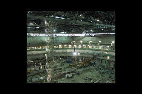
While this was going on, the 100 m diameter roof structure was built on the arena floor and, at the same time, the opportunity was taken to install all the M&E systems, including the main header duct, lighting ballasts and the voice alarm and evacuation system. The entire assembly was then strand jacked up into position. The massive operation was done in two lifts. “It was only when they started constructing everything on the arena floor that you realised just how gigantic everything is on this project. Prior to going to construction it was easy to forget the scale,” says Griffiths.
Of all the power requirements, the most difficult to predict was the stage power. Now that the client, AEG, has begun booking concerts a clearer idea of the electricity needs are beginning to be known. “The solution for show power must ensure that sufficient capacity is provided at all possible positions throughout the bowl to accommodate the most demanding of tours,” says McCarthy. “The solution provides dedicated plug-and-play switchboards while dealing with the issue of harmonic distortion and the need for mobile isolating transformers.
With the entire building able to hold 60,000 people at peak periods, the fire and escape strategy was another challenging aspect of the design. The vast majority of the construction didn’t fall under the usual standards applying to fire engineering, and it was clear from the outset that a bespoke fire-engineered approach was the only way that a suitable design could be achieved.
The design follows the guidelines in BS7974: Application of fire safety engineering principles to the design of buildings. Fire size and smoke production within the O2 are controlled by a combination of fire suppression, smoke management, fire resisting construction, control of fire load and other management provisions. There is no limitation of fire load in sprinkler-controlled or compartmented areas, but management control is necessary in open spaces. In other words, there is a specification of a maximum fire size when the O2 is occupied by the public. Thirteen fire scenarios were examined, and the extent of smoke movement was tested using simplified “zone models”. The results showed that none posed a serious threat to the occupants, and that existing smoke extract provisions could cater for the inclusion of the new development adequately.
The “worst case scenario” identified was tested further using CFD simulation. Provided certain conditions are met, it was found that there would be no detrimental effect on occupant safety by the inclusion of the new buildings within the O2.
One of the advantages of building within the Dome is there have been no weather delays. “Speed of construction has been good, they’ve been able to pour concrete continuously,” quips McCarthy. With just three months to go on the construction programme, work is well advanced. Glycol pipework for the permanent ice rink that sits at the centre of the arena is being installed. Unlike the water-cooled chillers used elsewhere, the flow and return headers from this run back to a dedicated ammonia chiller – a second-hand unit from the London Arena – more suited to the low temperatures required to maintain the ice.
The 96 executive boxes arranged on two levels around the perimeter of the music and sporting venue are now being fitted out. Their open-fronted design was a bonus to the servicing strategy. They will be conditioned by encouraging air from the Arena to be drawn through and out via an extract at the back of the space, rather than using a separate fan coil system.
AEG had been hoping to win the licence to open the UK’s first supercasino at the O2, and the services were designed to accommodate this had it gone ahead. “We could have had it up and running in 18 months,” says McCarthy. “There was capacity in the systems to fit out that area, casino or not.” Alternative plans for the 12,000 m2 space will now be found.
Commissioning of the services has begun, with flushing of the main distribution pipework almost complete. Inside the Entertainment district, contractors are fitting out the concessions and franchises. The fit-outs were added on to the base build contract at a later stage, and have relied on flexibility in the M&E design to accommodate changes as their exact size and nature has been finalised. “It’s been hard work as we’ve had to modify the M&E model to adapt to the changes, pushing the energy and electricity demands around to suit.”
However, the construction team now has fewer than 12 weeks to get the project completed and commissioned, ready for handover. McCarthy and Griffiths seem confident that the job will get done in time. But there is no place for complacency. There are currently 1,100 workers on site, doing everything from landscaping to fit-outs; there are also 80 electricians, part of whose task over the next two months is to install 3,200 light fittings.
Handover to the client will take place in May, but it won’t be until the inaugural concert in July that the success of the build will really be put to the test. Until then, everything remains tantalisingly hidden from view.
Positive Air Pressure Attenuators
Positive Air Pressure Attenuators
One of the more unusual problems resulting from building within the Dome is the fact that, for health and safety reasons, vent pipes for the soil pipework cannot discharge into the space beneath the tented roof.
Normally, vent stacks stabilise the air pressure within the soil stack to maintain it at near atmospheric pressure and reduce the incidence of “hydraulic shock” which damages trap seals causing them to leak or the build-up of positive pressures, in extreme cases leading to the trap water-seal blowing out of the fixture and leaking sewer gases into the building’s interior.
The solution to this has been to use air admittance valves and Positive Air Pressure Attenuators (PAPAs). Originally developed for high-rise buildings and resembling a large bladder within a cylinder, the PAPA unit acts like a shock absorber, absorbing pressure waves and stopping them bouncing around the plumbing system.
The units eliminate the need for vent piping and roof penetrations. “It’s the first time they have been used on this scale,” says David Griffiths of ME Building Services. “We got the manufacturer, Studor, to work with a team at Heriot-Watt University – who developed the PAPA system – to prove to Building Control that it would work.”
Source
Building Sustainable Design

No comments yet