


But of course, there’s no point making clean power if we’re still using too much of it, so energy efficiency is the leading edge of the campaign to reduce emissions.
Good progress has been made in this direction with the drive to minimise the use of air conditioning in favour of a more passive approach to the cooling of buildings. Passive design is most effective in new build, however this only represents 2-3% of the current UK building stock. For many existing buildings, and those for which some form of mechanical cooling cannot be avoided, other low energy options must be considered.
Ironically, while the greenhouse effect has been gradually raising temperatures across the UK, it seems to have also increased the potential for utilising evaporative comfort cooling during the summer. As part of the free cooling research currently underway at BSRIA, weather data was compared for the period 1946-66 and 1990-2000. This revealed that during the latter period, the dry bulb temperature in the London area during June, July and August stayed above 18°C approximately 10% more of the time than during the same months in the 1946-66 period. This increase of 10% coincides with a relative humidity of 60% or less for just over half of the time. This means that there is around a 6% increase during the summer period when evaporative comfort cooling systems can provide useful cooling in the London area.
The energy saving potential of evaporative cooling can of course be exploited on a year-round basis through the use of cooling towers in centralised chilled water systems. However, the greatest energy savings can be made when these systems are configured to provide free cooling during the cooler months of the year ie to shut the chillers down and allow the towers to supply the chilled water.
Free cooling
Tower-based free cooling can be achieved directly, by physically interconnecting the chilled water and condenser water circuits during free cooling operation, or indirectly by maintaining the chilled water circuit as a closed loop and rejecting heat to the cooling towers via a plate heat exchanger.
Alternatively, an indirect system may incorporate one or more closed circuit cooling towers or evaporative coolers. Use of these techniques is most effective when they can be incorporated into the design of a new air conditioning installation, however they can generally be retrofitted providing the site characteristics are suitable eg there is adequate cooling tower capacity. The requirement can put oversized cooling towers to good use since tower-based free cooling requires as much capacity as possible to be effective. This includes any standby tower that can be brought online during the free cooling season. A lack of tower capacity can rule out the use free cooling, especially if the winter cooling load is relatively high ie greater than 50% of the summer design load and/or the required chilled water temperature is relatively low.
Direct tower-based free cooling systems are widely used in the USA, where they were originally developed during the early 1970s. They started to appear in the UK during the early 1980s, and by the mid 1990s there were about 50 installed systems. This method of free cooling is very efficient, but requires a high standard of water filtration in conjunction with an effective operation and maintenance regime to ensure that no fouling or corrosion occurs in the chilled water circuit. In recent years the risk posed to the chilled water circuit has generally been regarded as too onerous, and there has been marked shift in favour of the indirect option.
Indirect tower-based free cooling systems typically reject heat to the towers by means of a plate heat exchanger (phe) as depicted in figure 1. Consequently, the condenser and chilled water circuits are at no point interlinked during free cooling and the risk of increased fouling and corrosion associated with direct systems is avoided. The penalty for using a phe is an increase in the overall chilled water to wet bulb approach temperature, and a corresponding reduction in free cooling availability. It is therefore important to design for a minimal approach to maximise efficiency, while also taking into account the corresponding increase in phe cost that goes up exponentially as the approach is reduced. This point is illustrated in figure 2, from which it can be seen that an approach of 1·5 K provides the shortest payback for a typical system. However, designing for an approach of 1 K will be more effective in the longer term. This is especially true where the extra plates required to achieve this approach can be accommodated in the same phe frame size, and also in installations operating on a 24-hour basis. It should be noted that the high phe surface area associated with low approach temperatures can lead to reduced water turbulence, which in turn, may increase the potential for fouling. Consequently, it is important that the phe supplier is closely involved in the selection process.
In addition to providing full free cooling, indirect systems can also be configured to provide simultaneous mechanical and free cooling, which is often referred to as load shaving. A load shaving system takes advantages of the shoulder months when a degree of free cooling is possible, but some mechanical cooling is also necessary to satisfy the cooling load. The basic operating principle is to direct the outlet water from the cooling towers into one or more phes, which have returned chilled water flowing across the adjacent side. Having passed through the phe, the tower water then supplies the condensers. Flow through the condensers is regulated to compensate for the low water temperature that would otherwise cause the chillers to trip out. Figure 3 shows the basic configuration of a system with multiple chillers/towers incorporating this method of load shaving. A detailed description of the system control will be included in the forthcoming BSRIA guide on free cooling systems.
Thermosyphon cooling
The deign of direct and indirect tower-based free cooling installations tends to be fairly bespoke to suit specific project constraints, and with this comes increased design and operational risk. As an alternative, there is a lower risk option called thermosyphon cooling, which offers all the benefits of an indirect system, in what amounts to a largely packaged solution1. This typically includes several slow reciprocating chillers, evaporative or dry coolers and a specially designed refrigerant pipe and valve arrangement. Thermosyphon systems work in the following way: when ambient conditions are sufficiently cool, the difference in temperature (and hence pressure) between the evaporator and condenser is used to drive refrigerant around the circuit without the need to operate the compressor. Refrigerant vapour formed in the evaporator is allowed to bypass the compressor and travel directly to the condenser where it is cooled. The condensate is then allowed to bypass the expansion valve and flow by gravity back to the evaporator where the process is repeated (figure 4).
While it is possible to have a single chiller thermosyphon system, multiple chiller installations connected in series on the chilled water side offer the greatest potential for free cooling across the weather year. A typical system with three chillers operates in the following way: At low load/ambient temperatures all units operate in thermosyphon mode. As the load/ambient temperature increases, the lead unit (last in the series) is switched to mechanical refrigeration and the compressor maintains the required chilled water flow temperature. In this respect, the installation operates as a load shaving system. The lead unit is the last inline and operates at the lowest chilled water temperature. Further increases in the load/ambient temperature will result in the next unit switching from thermosyphon to mechanical cooling, and under peak loads all the units will switch to mechanical cooling.
Whilst existing plant can theoretically be converted to take advantage of thermosyphon cooling, no such conversions exist in the UK. This is largely because to achieve worthwhile energy savings requires extensive and costly plant modifications to be made. In this respect thermosyphon systems differ from the direct and indirect tower-based free cooling techniques described earlier, which can represent a viable retrofit option.
Practical applications
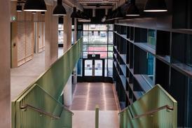
The advent of chilled ceilings/beams is perhaps the most significant development in the field of free cooling to have occurred in recent years. The use of relatively high chilled water temperatures made possible by chilled ceilings/beams has significantly increased the period each year when free cooling is possible. An example of a building that combines chilled beams and free cooling very effectively is the City Campus Learning Centre at Leeds Metropolitan University2, which was opened in 2000. Arup undertook the m&e design for the project, which had a challenging brief including an energy target of 129 kWh per m2/annum and an air leakage value of 5 m3/h/m2.
The result has been a very low energy design that is highly insulated, and incorporates fabric and glazing elements with low U-values (0·22 W/m2K for walls and 1·1 W/m2K for glazing). Night-time cooling of exposed open coffer ceilings provides a depression in the peak internal daytime temperature of around of 2·0-2·5 K. Displacement ventilation is used to cool most of the low to medium heat gain areas, whilst areas with a high density of computers combine displacement ventilation with chilled beams. Areas with the highest loads use active beams to boost the cooling performance.
Chilled water is supplied to the air handling units and chilled beams at a temperature of 14°C, which for much of the year can be provided by free cooling since the average air temperature across the year is 8°C in the Leeds area. The use of evaporative coolers to provide the chilled water provides a significant boost to the system efficiency. During hot spells when free cooling is not possible, mechanical refrigeration is used, which is able to operate relatively efficiently due to the high chilled water temperature. The drawback is the inability to provide dehumidification in the conventional way. This has been overcome through the use of a desiccant wheel system, which dehumidifies the supply air and ensures that the risk of condensation forming on the beams is avoided.
Building performance has been closely monitored since 2001, and has revealed that the energy target of 129 kWh per m2/annum can be meet, although average usage has generally been closer to 165 kWh per m2/annum. This has been attributed to teething difficulties with control strategy, which the client, represented by Garry East, deputy director of facilities at the University, is confident can be ironed out. He is working closely with the designer to optimise the m&e controls.
Downloads
Source
Building Sustainable Design
Reference
References
1All installations identified in the UK were designed/supplied by Star Refrigeration.
2The City Campus Learning Centre is one of several case studies that will feature in a forthcoming BSRIA guide on free cooling. See www.BSRIA.co.uk.
Postscript
Tom De Saulles is principal research engineer at BSRIA.

No comments yet