


Pressure independent control valves simplify hvac design and reduce system installation and running costs, says Terry Dodge
Pressure independent flow control valves are set to revolutionise the design of heating, cooling and air conditioning systems. They will simplify the design of a pipework system and so reduce design, installation and commissioning times, which will in turn make installations cheaper.
It’s also claimed that the new valves eliminate pressure fluctuations in a system’s pipework, which improves pump, boiler and chiller efficiencies, resulting in reduced running costs over the lifetime of heating and cooling systems.
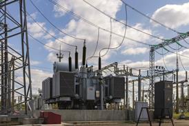
Pressure independent flow control valves (PI valves) have been in use in the USA for over a decade. The valves were initially developed to overcome pressure fluctuations in heating or cooling pipework systems in Boeing’s giant Seattle factory. More recently, they have been installed in the British Library (above) after a number of existing control valves failed – but they have yet to take off here.
In a conventional heating or cooling system, system pressures can be very complex and will change constantly as the system load changes. To overcome the effects of these pressure fluctuations in conventional pipework systems, valves, flow measurement devices and pipeline components are added in an attempt to bring the dynamics under control. Table 1 (below) summarises the type of components in current use and their function in comparison with a PI valve.
Conventional flow control problems
Conventional flow control valves regulate water flow by varying the pressure drop across the valve. So, for a flow control valve to work correctly, it must have a pressure loss across it. The following equation is used to calculate this pressure loss:
Q = Cv =DP/sg
(Q = Flow l/s
Cv= flow coefficient l/s @ 1 kPa
pressure differential
DP= Pressure loss across valve
sg= fluid density kg/m2)
The equation shows that any variation in the pressure across the valve will result in a change of flow rate. But, while guidance is available from manufacturer’s handbooks, guides and research organisations, no source gives adequate information about selecting control valve operation other than at peak design flow under stable pressure conditions – yet these conditions rarely occur throughout the life of the system.
Under part load, operating the actuator closes the gap between the valve plug and the valve seat, reducing flow through a control valve. The pressure drop across the valve increases as the flow rate decreases. When these pressure changes occur at the control valve, the pressure and flow change throughout the entire system of connected pipework. At each control valve on the system, pressure will either increase or decrease.
Sensors on these valves will constantly respond to adjust to these changes in pressure or flow in an attempt to maintain set point control and so the whole system becomes dynamic in operation. When this happens, inefficiencies also start to creep in with each variation from a set point. In addition, poorly selected control valves operating in an almost-closed position suffer from erosion to the valve control plug and seat.
Pressure independent control valves
PI valves solve the problem of varying flow conditions caused by pressure fluctuations within heating and cooling systems because the flow rate through them is not affected by pressure changes either upstream or downstream of the valve under load condition.
And, because they control flow accurately and only pass the required volume flow, no balancing is required to the piped heating system network, streamlining start up and commissioning.
The PI valves work by combining a modulating flow control valve and a differential pressure control valve in one valve body (see Figure 1, above right).
The pressure loss across the valve is a constant 37 kPa, irrespective of the load requirement on the valve – so the =DP/sg component of the above equation becomes a constant and flow variations are obtained by varying the flow coefficient (Cv) of the PI valve by rotating the control shaft.
With the differential pressure across the valve below 37 kPa, the PI valves act just like normal modulating control valves – the flow through the valve increases as the differential pressure across the valve increases.
Anatomy of a valve
Water first enters the PI valve through its modulating section at pressure P1 (system inlet pressure). This section contains the control shaft, which has a carefully engineered slot for the accurate linear flow control. Rotating the control shaft alters the water flow rate.
A port in the modulating section also allows water at pressure P1 to enter the differential pressure section of the valve. There is no flow through this section. The section has a spring-balanced piston which functions to maintain a constant differential pressure (P1 – P2, where P2 is the modulating system downstream internal pressure) across the control surfaces in the modulating section. This works because the total pressure of water flowing through the pipework is equal to the sum of its static and velocity pressures.
Flow rate
The relationship between pressure and flow rate over time for conventional and pressure independent valves is shown in Figure 2. It compares the flow rate through control valves on two secondary circuits – one fitted with a conventional control valve, the other with a PI valve.
The graph shows the flow rate through the PI valve is steady, while the flow rate through the conventional valve is constantly overflowing and being readjusted via the control. This is typical of conventional pressure-dependent control valves and is one of the main factors for the poor performance of installed systems.
PI valves are issued with their own calibrated flow rate certificates for the modulating section settings. Thus a flow rate can be found at any setting of the control shaft. This simplifies valve sizing, since all an engineer needs to know is the flow rate required and the maximum differential pressure across the system.
Each PI valve comes with its own pressure/temperature test plugs already fitted to the body of the valve. These plugs are fitted to the upstream and downstream sides of the modulating section and a third to the valve outlet.
Commissioning is a simple matter of checking at the test plugs for pressure and the differential pressures to verify the pressure drop. This same test can be used at any other time throughout the life of the PI valve to check it is working correctly.
Designing for PI valves
Applying PI valve technology into heating and cooling system design simplifies the design process and reduces the risk of control valve failure.
PI valves provide the principle method of load control in heating systems by controlling the water flow. Water temperature and pump pressure are used as a secondary method of control.
Figure 3 shows a schematic diagram of a heating system where water flow is controlled using PI valves.
As the PI valve will only pass the flow rate demanded, and that flow rate can be verified, there is little or no water balancing required other than checking that there is sufficient differential pressure at the index PI valve (the PI valve furthest from the pumps, or the valve on the ciruit pressure losses are the highest).
Although the schematic diagram is shown in a simple singular format, the same principles will apply for multiple combinations of air handling units, fan coils, radiators, under-floor heating coils and other components. In all cases, the need for flow measurement and balancing devices is eliminated, thus simplifying systems.
The system in Figure 3 shows a run of three boilers, each with a PI valve on the return connection so the water flow into each boiler can be set at the flow rate required by the manufacturer for maximum operating efficiency. Actuators on the PI Valve are set to ensure the valves do not open beyond the flow rate required. When the system operates at partial load conditions, the water flow rate is reduced and a boiler, or combination of boilers, will be signalled to switch off.
The actuator on the PI valve will shut off the water flow through the boiler. Once the valve has closed, circulating water will only pass through any firing boiler to ensure the cooler return water does not mix with the hotter flow water emerging from the firing boiler(s). This method of control and isolation can be tailored to sequence any boiler as the lead boiler.
For the air handling unit, the schematic shows a constant temperature variable flow circuit. This maintains the highest flow temperature to allow the air handling unit coils to operate efficiently, with isolating valves fitted to the flow and return connections for maintenance purposes, and a PI valve located on the return outlet from the heater battery.
Fan coil units, too, require a constant temperature variable flow hot water supply. However, they often only use very small volumes of water for heating, which causes commissioning and balancing problems. They also reduce system efficiency as, under part load, the system circulates excess water.
Systems in practice
A simple way of ensuring water flow conditions remain efficient is to decouple the fan coil pipework sub circuit and incorporate a small circulating pump for the fan coil sub-circuit. Figure 3 shows how this can be done using a PI valve on the return from the fan coil sub-circuit. This is set to open only when the flow temperature starts to decrease, which will ensure only sufficient water will flow into the fan coil sub-circuit under any load condition. Under part load conditions, the separate circuit ensures a minimum flow rate and design temperature differential is maintained.
The principle of decoupling a circuit can also be used to supply under floor-heating coils. However, for this application a PI valve is used to reduce the flow temperature to the coil. This is set up so that when the flow temperature reaches the required level, the control system starts to shut down the flow rate through the PI valve so less hot water enters the decoupled circuit.
A similar set-up can be used to modulate the flow temperatures to a radiator circuit. The principle advantage of using this method is that it allows the water temperature returning from the heat emitter to be low, which helps reduce the system return temperature and thus ensures that condensing boilers can be run in their condensing mode for a full heating system.
Downloads
Source
Building Sustainable Design
Postscript
Terry Dodge is technical director of Raxcrest Valves. For more information on PI valves, visit www.raxcrest.co.uk

No comments yet