


The need for high quality well integrated documentation has become more and more pressing and the limitations of pure CAD systems increasingly apparent. Today's building industry demands the kind of transparency and flexibility which goes way beyond traditional CAD offerings. Additional to this two current trends, facilities management and 3d, cannot be addressed by standard drafting packages without a specialised and well integrated application.
The ideal would be a system which offered a range of functionality, for example automatic positioning, alignment of luminaires, loudspeakers, automatic creation of cable containments in 2d and 3d, and an automatically generated drawing legend. But more than that it should include a project and drawing management facility, and have the ability to automatically transfer relevant drawing data, like title, indices and approval status into the drawing file.
All of this is a vast improvement on the standard drawing-board and has become standard in more advanced CAD applications for building services. Unfortunately users often find that these systems take some time to get to grips with. However, there is a development from Germany which may offer a solution, elcoCAD R4.
This offers a number of useful developments and is achieved partly with built-in software, and partly by interfacing with other packages. For lighting calculations elcoCAD R4 comes with bidirectional interfaces to DIALux and RELUX. In elcoCAD R4, the shape of the room is transferred from the floor plan to the lighting calculation system, and the exact position of the luminaires, including their 3d co-ordinates, dimensions and load are automatically transferred back to the floor plan.
The system supports ETS/2, the official software package for European Installation Bus (EIB) technology, by including data exports of all EIB items. Microsoft Word and Excel are used for the creation of lists and reports and a configurable Excel import module is included, for importing specification sheets into elcoCAD's project database.
EPI is a bidirectional interface that allows data exchange with software packages for electrical calculations (BS 7671) for protection, cable, discrimination etc. If you need to create circuit diagrams elcoCAD R4 is shipped with an interface to ePLAN 5 and other packages for electrical control diagrams. Electric circuit information is automatically generated from the electrical installation extracted from the floor plans and can be printed as a distribution schedule.
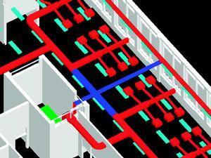
A big issue in electrical installation engineering is always cable routing. An important part of the system's philosophy is stepwise refinement which enables the user to add information at various levels of detail as the project progresses. For example the built-in cable manager allows the user to define the basic structure of distribution boards and circuits. In the first step the user selects the required devices by simply clicking on them, thus connecting them into the desired circuit. Cable length, the number of devices on the electric circuit and the cumulated load are displayed online.
Having defined these basic structures, the system now has enough information to generate all the output. If it is necessary to document the exact cable routes or to get precise cable and conduit quantities, there is a function to draw 2d/3d polylines and link them to the cable manager. The system offers an optimised algorithm for finding the shortest connection between two points. This supports networks with loops as well as user-defined redirection, where a specific connection is disallowed.
The software is prepared for all common cable systems while other systems can be configured manually. Because of its flexible design elcoCAD R4 can be adapted to nearly any kind of requirement – and flexibility is a very important issue. An estimated 80% of the design process in the building industry involves altering completed work. elcoCAD caters for such changes by dynamically updating the online-database; adjusting length or location changes automatically, whenever the user moves a socket, luminaire or cable.
Unlike any other industry, the construction industry has a tendency to resolve problems on site, resulting in increased costs for co-ordination. For this reason 3d and clash detection have become hot topics. Unfortunately 3d-modelling is a time consuming and expensive technique if you are using a basic CAD product. While the user is working strictly in 2d, newer software will generate a complete 3d model in the background, that can be used for wall elevations and 3d analysis. The brand new interface to NavisWorks 3 can be invoked for sophisticated visualisation, walkthroughs and automatic clash detection.
Source
Building Sustainable Design

No comments yet