Prewett Bizley consider the design and installation of the building services in the eco-makeover of an Edwardian home
As well as substantially improving the performance of the building fabric with insulation and air tightness measures discussed in the previous posts, we have also been mindful of the design and installation of the building services.
Domestic hot water design in the UK is not normally discussed in any detail by building designers and more often than not the site plumber is left making the best of a bad job. As for mechanical ventilation with heat recovery (MVHR), while one can find a host of suppliers of kit nowadays, there are very few designers willing to work on one off projects.
Mechanical ventilation and heat recovery
Before I commence I should note a debt of gratitude to the Green Building Store who are supplying the components and to Andrew Farr in particular who has engineered our system.
It might sound rather obvious to say it but for systems like this to work effectively it is important that they are designed and installed by competent persons. Andrew is one of few such people in the UK and we consider his input an absolute essential rather than an optional extra.
Based on his experience and knowledge we have chosen a unit called the ‘Focus’ and made by a German company Paul, who are recognised as leaders in this field. It is a new model and combines excellent efficiency with improved user friendliness and flexibility. It uses a patented ‘cross-flow’ device that allows the transfer of heat from one stream or air to another without the two flows actually coming into physical contact or mixing with each other. It is possible to recover up to 90% of the energy stored within the rejected air. While a modest amount of electricity is required to run the two fans the ratio of energy used to energy saved is around 1:20. Of course that assumes the house is highly insulated and airtight in the first place.
For our project we started by planning where to locate the MVHR unit. While the large loft over the main part of the house seemed an attractive option in terms of a space saving, this would have required making access both easy and safe as well as taking the supply and extract ducts through the roof. We also felt that the relationship of the loft to the rest of the house may have resulted in longer duct lengths compared to other solutions which may in turn have lead to efficiency reductions. All in all this looked like a risky option for our project.
The existing house was generously planned anyway and we felt that it could accommodate the space for the unit. Doing this meant that we could locate it towards the centre of the plan thereby minimising the length of duct runs.
The attached diagram indicates the proposed duct layout in relation to the house. Fresh air is distributed to living spaces by the blue pipes which are located within the joist zone of the main floor and within a thickened stud wall. The location of the air input nozzles has been chosen to encourage air movement throughout each room before it exists under the door and then drawn towards rooms with extraction.
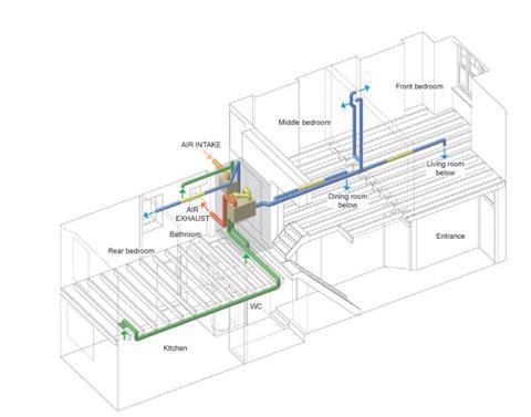
Stale air is extracted from the kitchen and bathrooms via the green pipes. Again the locations of the extract points have been selected in order to maximise air movement in those spaces and avoid dead areas where air may stagnate.
Careful consideration of placement of the ducts and nozzles is important in order to achieve an efficient and system that delivers high levels of comfort. Generally we have located the duct terminations at high level at the top of walls or in ceilings. Undercut doors allow air to escape from living rooms and enter bathrooms or kitchen. Planning the air paths helps maximise the feeling of freshness that MVHR can offer. A high level of air quality is an important part of the increased comfort levels that lie at the core of Passivhaus design philosophy. When one visits Passivhaus buildings, this feeling is quite tangible – no stuffiness or lingering odours.
The galvanised steel ducts are rigid to reduce friction and drag and they are assembled with push fit connections that self seal air tight. By the way the yellow sections in the diagram represent short flexible lengths used to attenuate noise transfer so that ‘cross talk’ is not apparent between rooms.
The diagram also shows the stale air exhaust and the fresh air intake. Users of Passive House Planning Software will be aware that designs with long intake and exhaust ducts within the building envelope pay a heavy price in the estimated system efficiency. While this loss can be mitigated by installing ever increasing amounts of insulation around the duct, one quickly runs into problems in terms of physically installing the insulation. And that job needs to be done with care in order to avoid trapped air pockets or any gaps that allow air or moisture to approach the duct face. Failure to do this can result in interstitial condensation forming around the duct, a problem both for heat recovery performance and for longer term maintenance.
We have ended up with ducts around 2.5 m long with 50mm insulation around them. The ducts couldn’t have been reduced in length any further as we need to achieve good separation of the duct terminals in order to avoid stale air finding its way into the intake.
Domestic hot water
A paper presented by Alan Clarke and Nick Grant at this year’s Passivhaus conference held in Germany highlighted how poorly design of hot water systems can result in energy losses approaching the entire heating load for a Passivhaus. According to their well argued paper, conventional UK plumbing practice can result in a doubling of energy used for hot water production in very well insulated houses.
We studied both while planning the plumbing system on this project and we have used the services of Nick Grant of Elemental Solutions to help specify the final system. His experience and advice will hopefully ensure that the future tenant will enjoy both good flow rates of water and very low energy losses.
In the first instance we located the boiler and hot water tank adjacent to each other (to reduce losses between the two) in close proximity to the bathroom, WC and kitchen (in order to minimise pipe runs between the tank and the taps). The attached diagram shows how long each pipe is to each fitting and how much ‘hot’ water is stored in each these ‘dead legs’.
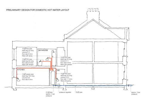
Based on a measured incoming water pressure of just over 3 bar, we believe that the water pressure at the tank will be a little over 2 bar. Given that sort of pressure and short pipe lengths it is possible to use small bore individual pipes to each appliance, the logic being that the volume of water in the pipe is very small and will therefore dissipate only small amounts of heat when standing by. When a tap is opened the hot water will arrive very quickly too so users won’t need to waste lots of luke warm water while waiting for the hot water to arrive. We intend to insulate all of these pipes with the hope of further reducing wastage of luke warm water, although some would argue that dispensing with insulation would not make much difference. We will also insulate the cold feed to the kitchen to avoid wastage of similarly luke warm water when waiting to fill a glass of water say.
For those wishing to know more about domestic hot water design I recommend a visit to the AECB website. Two volumes of guidance and the paper referred to above are available for free download. They are useful to the novice and experienced designer alike I think and are very well written. In fact their website is a rich source for anyone interested in low carbon building.
Robert Prewett is partner at architect Prewett Bizley






No comments yet