


Building looks at how London’s most historic crossing was replaced with a relatively overlooked concrete bridge
Before there was London, there was London Bridge. The capital’s oldest crossing was built before the city itself, by the Romans almost 2,000 years ago, to allow troops to press northwards on their invasion of Britain. It marked the most easterly point of the river where it was still narrow enough to build a bridge, and what is now the capital city began as a market on its northern side.

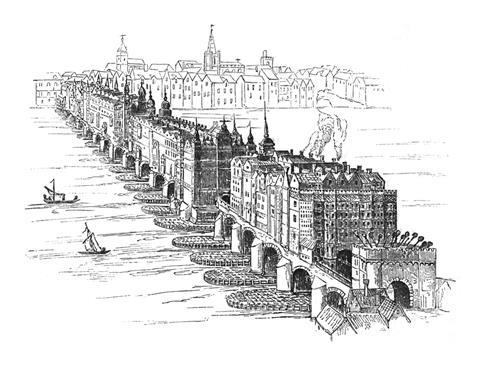
This early wooden structure was replaced over the centuries by several Anglo Saxon and Norman bridges, and later by a stone bridge in the 12th century which became famous throughout Europe for being almost entirely covered in houses, shops and even a church. It remained the only crossing of the Thames in London for more than six centuries, before Westminster bridge was added in the 18th century.
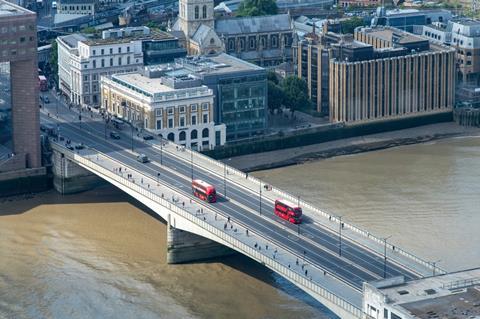
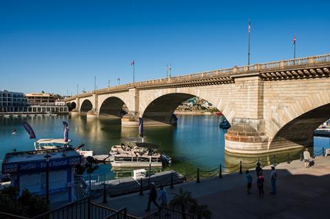
Today’s bridge was ordered in the late 1960s and designed by Mott McDonald predecessor Mott, Hay and Anderson. It was built by Mowlem, the contractor bought by Carillion in 2006, while the 19th-century crossing which it replaced was bought by an American businessman and improbably rebuilt in Arizona, where it still stands.
Compared with the impressive history of its antecedents, the modern London Bridge could to some look, frankly, a bit drab. The brutalist concrete structure is now relatively overlooked, lacking the visual charisma of many of the capital’s more famous bridges.
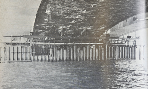
But the challenge of building it at its unstable downstream site, requiring the construction of 20ft wide concrete columns sunk 70ft below the riverbed, should earn it more credit. Below is Building’s summary of what it took to complete the task, published on the day that it was opened by Queen Elizabeth II on 16 March 1973.
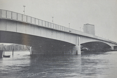
Feature, 16 March 1973
The new London Bridge, which is officially opened today, replaces the bridge built in 1831 by John Rennie, the facings and balustrades of which have been sold and reconstructed at Lake Havasu on the Colorado River in Arizona. The complex task of demolition and construction was further complicated by the need to meet a variety of river and road traffic requirements, the work in no way being allowed to impede or interfere with prescribed volumes of pedestrian, vehicular and river traffic on and around a site that was already restricted by adjoining buildings.
History
The first London Bridge, probably of rudimentary construction, was built in Roman times and, with its successors, remained the only bridge over the tidal reaches of the Thames until 1749 when the first Westminster Bridge was constructed. The first stone bridge, commenced by Peter de Colechurch in 1176, took 33 years to complete and stood for more than 600 years before being replaced by Rennie’s bridge in 1831. Colechurch’s bridge with 19 piers had houses and shops along it and was situated in line with Fish Street Hill in the City, about 50 yards downstream of today’s bridge.
Rennie’s bridge was constructed in 1825-31 with five arches varying from 130 feet to 152 feet and was 56 feet wide originally but increased to a width of 69 feet in 1902 with granite corbelling. The bridge weighed some 130,000 tons, the arches being constructed in granite and the piers and facades faced in granite, and within one month of completion the whole bridge settled approximately 12 inches on the downstream side and slow settlement continued to take place in subsequent years. However, in 1831 a Parliamentary Commission, consisting of Telford, Walker and Tierney-Clark pronounced the bridge safe despite the settlement.
By the early 1960s the bridge had again become too narrow, this time for the demands of vehicles as well as pedestrians and Mott, Hay & Anderson were appointed in 1963 to carry out the widening of the bridge on the upstream side by 25 feet. However, the continuing settlement was causing cracking in the stone arches and spandrels and a site investigation of the strata on which the bridge was founded revealed that the ground was so heavily loaded that any major disturbance during remedial work or bridge widening operations would create a structural hazard beyond the bounds of prudence. In 1965 therefore, the engineers recommended against widening and proposed a new bridge.
In 1967 the City Corporation obtained a Parliamentary Bill authorizing replacement of the old bridge by a new one and design work started immediately, the contract to demolish the existing bridge and to build the new one being awarded to Mowlem on 5 October 1967. Work started on 6 November 1967, the original construction time of 54 months being extended to allow for additional work, river obstructions, design modification and latterly for the national building strike. In April 1968 the City Corporation sold the facework of Rennie’s bridge to McCulloch Properties Inc for rebuilding at Lake Havasu City in Arizona, USA. Mott. Hay & Anderson were appointed as engineers for the reconstruction which was completed in October 1971 and opened by Sir Peter Studd, London’s Lord Mayor.
It was required that during construction of the proposed new bridge shipping movement up to 300 vessels a day should be maintained, a minimum of two 100ft-wide openings, one having 20ft headroom over 60ft width, being required. Facilities for pedestrian and road traffic had to be fully maintained during construction except for limited periods at night or during weekends, road traffic being 20,000 vehicles per day, and 17,000 pedestrians per hour during peak periods.
The bridge was to be 107ft wide (the available distance between existing buildings), to have dual three-lane carriageways each 30ft, and footways 21ft wide. (downstream) and 15ft wide (upstream) while provision was also required for additional pedestrian capacity at a future date. The required navigational widths could only be maintained, while building new river piers, by keeping these to two slender piers, each close to piers of Rennie’s bridge. The conditions required a three-span structure with a centre span of 340ft and it was decided to allow a headroom of 29ft 6in above high water, to match that of Waterloo Bridge.
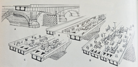
The increased width of the new bridge made it possible to design and build the structure in the form of four longitudinal parallel bridges, each one quarter of the final total width. These strips could be built and brought into use one at a time. There was little to choose in price between steel and concrete as the principal material but concrete was chosen partly to save maintenance, and partly because of its architectural advantages in the city surroundings.
Additional pedestrian capacity in the future was allowed in the design by making provision for an enclosed, glazed, high-level walkway, supported on columns in the central reservation.
Navigational requirements precluded support of demolition or construction staging from below, so temporary steel overhead gantries were specified and designed by the engineers which would serve both for support of the old arches during demolition and to support each quarter of the new bridge during erection.
The cross section of the bridge was fixed by the final carriageway requirements, the temporary carriageway requirements, the shape and position of the old bridge and the planned construction sequence.
The solution which fulfilled all conditions was a cross section consisting of four parallel concrete box beams, to be assembled individually from prefabricated sections and connected transversely on completion. By construction of the two outer box beams and opening these to traffic before major demolition of the old bridge to make way for the two inner box beams, continuity of vehicle and pedestrian traffic could be maintained.
While continuous box beams throughout the length of the bridge were considered, it was decided that cantilever-cum-suspended span construction offered more advantages.
To obtain the grit-blasted finish specified by the consultant architect, Lord Holford, it was decided, following site trials, to use a grey granite aggregate from Creetown, Scotland, and white sand from Hunables, Essex, with ordinary Portland cement.
Foundations
It was necessary to found the new bridge in the clay well below the heavily overloaded material under the old bridge’s foundations and to obtain safe bearing pressures for the new foundations close to the old ones, it was also necessary to extend the base of the new foundations under the old foundations. It was essential to excavate through the overloaded clay in such a way as to minimise possible danger, and to meet these considerations it was decided to found at minus 86ft OD, and to construct each pier foundation of a row of four large diameter shafts, only one shaft in each row being opened at a time.
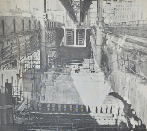
Each shaft was designed to begin at 12ft diameter in a 20ft square dewatered cofferdam (70ft piles with one wall in contact with existing pier). Prefabricated double-steel lining segments were fitted in, the annulus being filled with concrete. The shaft was then extended down, 2ft at a time, its diameter increasing in steps to 20ft and the base then under-reamed to a diameter of 26ft 6in. Finally the completed shafts were concrete filled. Most of the Mowlem mining engineers for these deep workings came to the bridge from the Victoria Line contract.
The outer shaft foundations were extended up, each as a separate column to support one quarter of the bridge, each column being designed to carry a vertical reaction of 2,490 tons, a lateral load of 23 tons and a 62-ton longitudinal load.
After construction of the outer columns and outer quarters of the new bridge, demolition of the old bridge continued to arch springing level before the two inner shaft foundations were placed. Finally the pier was completed by forming monolithic reinforced concrete wall between the two original columns, the granite facework for the piers being placed in position after completion of the concrete work.
The south abutment and its foundation were designed on the same lines as the river piers; however, as loadings were less, only three shafts were required. The north abutment is founded on two foundation shafts only, due to the presence of running tunnels of the London Underground Northern Line, which made the siting of other shafts impossible. The possibility of greater settlement was minimised by making the abutment base above the shafts cover the maximum possible area where it founded on gravel. This abutment had to be constructed under a temporary steel dock to permit maintenance of traffic above.
Superstructure
As working space on the site was virtually non-existent and approach by road would have been severely restricted by normal traffic, it was decided to construct the four box beams by casting segments at a suitable site and bringing them by barge to the bridge where they would be hoisted into position from the construction gantry.
An overall length of approximately 9.7ft was fixed for the segments, this giving a maximum weight at the haunches of approximately 70 tons, and a total of 35 segments in each of the four main spans.
Individual segments were reinforced for traffic loading on the top slab, this being made continuous through the joints which consisted of four inches of fine concrete.
Mowlem’s Docks Division established a casting yard three miles downstream in the Surrey Commercial Docks to prefabricate bridge segments which were cast open-end-up, special turning hoists having to be provided to turn each unit weighing up to 75 tons through 90 degrees before loading on to barges.
Assembly of segments was effected, one box beam at a time, by suspending a complete set in position from the steel gantry. These were then levelled, jointed and stressed with a system of “external” 0.7in diameter steel strands. Additional cables over the piers and in the side-spans were accommodated in ducts. Maximum strand length is 380ft and the largest number of strands in any one section of one box is 400. In all about 150 miles of steel strands were used.
During erection an electronic monitoring device was used to record simultaneously the more critical gantry hanger loadings and span level changes during the stressing operation. PTFE/stainless steel sliding bearings were used at the abutments and at the ends of the suspended span. Expansion joints have stainless steel hooded comb castings.
Finishes, services and cost
The river piers and abutments are faced in selected axed granite from Cornwall while the exposed concrete on the elevations of the bridge was lightly gritblasted to produce an accelerated weathering effect. Parapets are clad in polished granite from Devon, and are surmounted by a stainless steel handrail while footways are paved with York stone slabs with granite kerbs.
The new bridge incorporates some 100 longitudinal ducts for GPO, LEB and CEGB services to a gross loading of 800 tons. Heating cables have been incorporated under carriageways and footways and provision has been made for floodlighting the bridge by fluorescent units fitted under the parapet base.
The cost of the £5.25m bridge to the public, ratepayers of London and taxpayers is nil, since it is all met by the Bridge House Estates Fund of the Corporation of London, which derives the bulk of its £1m yearly income from the City’s estate rentals.
More from the archives:
>> Nelson’s Column runs out of money, 1843-44
>> The clearance of London’s worst slum, 1843-46
>> The construction of the Palace of Westminster, 1847
>> Benjamin Disraeli’s proposal to hang architects, 1847
>> The Crystal Palace’s leaking roof, 1851
>> Cleaning up the Great Stink, 1858
>> Setbacks on the world’s first underground railway, 1860
>> The opening of Clifton Suspension Bridge, 1864
>> Replacing Old Smithfield Market, 1864-68
>> Alternative designs for Manchester Town Hall, 1868
>> The construction of the Forth Bridge, 1873-90
>> The demolition of Northumberland House, 1874
>> Dodging falling bricks at the Natural History Museum construction site, 1876
>> An alternative proposal for Tower Bridge, 1878
>> The Tay Bridge disaster, 1879
>> Building in Bombay, 1879 - 1892
>> Cologne Cathedral’s topping out ceremony, 1880
>> Britain’s dim view of the Eiffel Tower, 1886-89
>> First proposals for the Glasgow Subway, 1887
>> The construction of Westminster Cathedral, 1895-1902
>> Westminster’s unbuilt gothic skyscraper 1904
>> The great San Francisco earthquake, 1906
>> The construction of New York’s Woolworth Building, 1911-13
>> The First World War breaks out, 1914
>> The Great War drags on, 1915-16
>> London’s first air raids, 1918
>> The Chrysler Building and the Empire State Building, 1930
>> The Daily Express Building, 1932
>> Outbreak of the Second World War, 1939
>> Britain celebrates victory in Europe, 1945
>> How buildings were affected by the atomic bombs dropped on Japan, 1946
>> Rebuilding the House of Commons chamber, 1945
>> Planning the postwar New Towns, 1945-46
>> The Festival of Britain, 1951
>> The world’s first nuclear power station, 1956-57


No comments yet