It is recognised that variable speed pumps offer significant potential for energy savings. By varying the speed of the pump to match system demand, pump energy consumption can be significantly reduced. Due to the cube law relationship between pump speed and energy consumption, small reductions in pump speed lead to dramatic reductions in energy consumption. Estimated pump energy savings of between 60-70% have been predicted for typical building heating and cooling applications.
However, designers face the challenge of utilising the undoubted energy saving potential of variable speed pumps, while avoiding excessive expenditure elsewhere in the system – and without risking embarrassing operating problems.
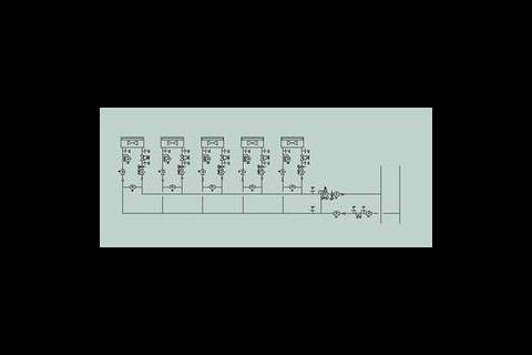
So what are the main design challenges? The common design solution for a branch in a fan coil or chilled beam system is as shown in figure 1. The differential pressure control valve (dpcv) is there to compensate for variations in the total branch pressure caused by the movement of control valves, or variations in pump speed. The dpcv will maintain a constant differential pressure across the branch, regardless of what's happening elsewhere in the system.
This solves one problem, but the designer must then grapple with a number of other issues. First is the shut off pressures for two port valves. A two port valve, unlike three or four port valves, has to be able to shut off against the maximum possible pressure differential in the circuit. In the example shown in figure 1 this would be the pressure differential controlled by the dpcv. Therefore, larger, more powerful actuators than those used in constant volume systems, are required to guarantee effective closure of control valves.
The second challenge, is the ability to achieve control authority across modulating two port valves. Optimum modulating control is achieved with an authority of at least 0·5 (authority being the ratio between the pressure drop across the fully open control valve and the circuit it controls).
For a two port valve the controlled circuit extends back to the dpcv. Good control practise requires the two port valve to have as much pressure loss as the rest of the circuit it controls. In practice, it is seldom possible to obtain such highly resistive control valves. Control authority is frequently compromised (values between 0·2-0·3 being accepted) which results in a control characteristic approaching on/off.
Balancing act
Another consideration is whether to install balancing valves. In theory, balancing valves have little function in a system where circuit resistances are constantly changing. Their inclusion is usually justified on the grounds that during system start-up when all circuits are calling for flow, a good flow balance is essential. If the system is out of balance then it will need to run for a much longer period before even temperatures are achieved thereby reducing energy efficiency. However, by retaining balancing valves and adding dpcvs and two port valves with larger actuators, the capital cost will increase significantly compared to constant speed/volume circuits.
A modular solution
The ideal solution to the problems identified above would be to install a dpcv on every terminal branch. This would mean that two port valves would only need to control or shut off against the local pressure in the terminal branch, and balancing valves would be superfluous. However, since dpcvs are expensive compared to regulating valves, and should also ideally be accompanied by separate isolating and flow measurement facilities, this option would be prohibitively expensive.
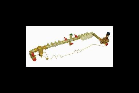
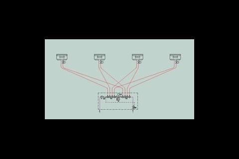
An effective compromise is to modularise the system in such a way that groups of terminal units can share facilities. Such a system is shown in figure 2. By utilising distribution manifolds and using a flexible plastic-coated aluminium pipe such as Alupex for run-outs, the aforementioned design issues are largely resolved with no increase in overall system cost.
The main features of the arrangement shown in figure 2 are:
- A large bodied strainer to remove circulating system debris before it has a chance to cause blockages in terminal units, regulating valves or control valves.
- Flexible, plastic-coated aluminium pipe, which can be installed in single lengths between the manifold and terminals thereby reducing installation time.
- A central flushing bypass and drain so that each terminal can be flushed and cleaned from a single location.
- A central air vent so that the entire arrangement including the terminals can be vented from a single point.
- A return manifold with optional balancing valves (or on/off two port valves) incorporated on to each port.
- A single dpcv to maintain a constant differential pressure between flow and return manifolds.
This centralisation of flushing, venting and flow balancing facilities makes system commissioning easier and less prone to problems compared to a traditional system with copper run-outs to terminals. Furthermore, in comparison to the typical variable speed/volume solution outlined in figure 1, there are a number of benefits.
First, the two port valves need only to be sized to shut off against the pressure drop across the manifolds. This value will usually be only marginally higher than the pressure drop across the terminal unit, and will be potentially a much lower value than the pressure drop across the entire branch.
Second, the two-port valves in modulating applications can be selected such that a control authority of 0·5 is retained. Where on/off control is appropriate, control valves can be integrated within the return manifold to give increased cost savings. Also since each circuit fed from the manifolds has the same differential pressure, then, provided that similar lengths of flexible pipe are installed and terminal units are identical, the flows should self-balance. As individual two port valves close, flows to other circuits should change in the same proportions. In some situations this opens up the option of omitting the regulating valves with significant cost savings.
As a technical solution, it can be seen that modularisation simplifies a number of otherwise difficult technical decisions. Although it could be classed as an innovation, and therefore, deserving of caution from engineers, in fact all of the components used are regularly specified and installed in modern buildings; the only difference is the way in which they have been arranged.
Manifold distribution has been around since the 1970s when it was applied to microbore systems. Even the Alupex pipe, which may be new to some UK engineers, has been in use since the late 1980s in other parts of Europe. Its properties (12 bar pressure rating, 95°C temperature, expansion properties similar to copper, no sagging, 100% oxygen diffusion barrier) make it a suitable alternative to copper for run-outs to terminals.
Rapid evolution
This type of system is currently being designed into a variety of projects in the UK, so that a growing number of case study projects are available for analysis. Although it forms a better design solution for the reasons explained, it is also extremely attractive to installing contractors thanks to the significant savings in both labour and programme time.
It's a new technique, but one that is evolving fast. Already it's possible to order complete modular arrangements prefabricated in insulated boxes to further reduce site installation time.
Source
Building Sustainable Design
Postscript
Chris Parsloe is technical manager of SAV Valve Systems. For more information e-mail: savukltd@aol.com







No comments yet