Foster's sculpture has one big advantage over Andre's bricks: it works as a real roof on a residential block. Viewed from above, its organic curves will undulate in and out, rhyming with the riverside frontage; from the side, the roof forms an arc from front to back; and viewed from the front, it forms a series of hills and valleys.
Foster and engineer Arup have teamed up to take roof design to a new level. Both firms worked together on London's other curvaceous creations, City Hall and Swiss Re. These two office developments featured curved facades but were capped by relatively simple domes. Albion Riverside has complex curves in all three planes. This immensely challenging shape has been made possible by computer modelling – but coming up with a pretty model is one thing; turning it into practical, buildable reality is another.
"The shape of the building is derived from shell forms," says Justin Nicholls, associate architect responsible for the external envelope. "It's a logarithmic spiral." This describes a spiral that unwinds progressively more gently the further you get from its centre. The building looks like a human embryo in plan; its east end is tightly curved and unwinds to a much softer, straighter curve on the west side. Nicholls says this shape was derived from the logistics of the site, and satisfied the developer's requirement for a range of apartment sizes. At ground- and first-floor level there will be shops, a restaurant and a leisure centre.
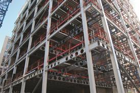
Nicholls describes the building's structure as a "spaceship on legs". The 11-storey concrete frame sits on giant columns splaying out from the base of the main structure two storeys up. The columns are arranged in pairs, and converge at a single point on the ground. Four equally spaced cores provide structural support and house the lifts. The floor-plate bulges out in front of each core to maximise space, giving the building's frontage its wavy appearance. This sinuosity is repeated on the roof as it rises over the cores to accommodate plant machinery.
The building was designed using the same computer-modelling techniques as those used on Swiss Re and City Hall. As there are virtually no straight lines in any of these buildings, a single reference point is created. This enables a 3D model to be set up by defining every part of it by its spatial relationship with that point. All the consultants and contractors base their designs on this model, but because everyone has a different CAD system the architect constantly checks their work to ensure it matches up. On site, specialist surveyors set the building out using lasers.
The team tried panels and aluminium sheets for cladding. In the end, the solution was a material associated with giant sheds
Because of its complexity, procuring the roof needed great care. A joint venture was formed between Austrian firm Waagner Biro, responsible for the roof structure, and Prater, which will install its cladding. This was vital to prevent problems in one area being passed onto the other specialist. "It's possible to make the steelwork cheaper, but the cladding more expensive and vice versa," says Hayden Nuttall, associate director at Arup. "We asked them to work together and pointed out the difficulties they have to face to avoid problems that other projects have. So far, it's worked very well."
This approach made the roof affordable. "We tendered to a whole range of people: both to joint ventures and as separate packages. What we saw was that more experienced contractors worked out cheaper," says Nicholls.
The team worked closely together to make the roof as easy as possible to build. Fortunately, they solved the buildability problem early on. "We had a breakthrough," says Nuttall. "We had to work out how to generate the roof shape. We could have had hundreds of arcs, but in the end we used just two (see box over). That was the key to unlocking the whole thing. Whenever you have something complicated like this you need to break it down to something very simple." Computer modelling helped the team to test, inform and develop the idea into a solution.
Having sorted out the geometry and structure the issue of the cladding had to be resolved. Nicholls says a primary requirement was a "shiny metallic surface". Initially the team looked at using a panellised solution: "We found very substantial variations in panel size," says Nicholls. "We looked at trying to use 30 different panel sizes; we found we would've needed thousands." The team then plumped for a more traditional idea. This was aluminium sheets welded together on the roof supported by plywood. Just two weeks before the tender was let the team changed their mind again.
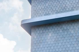
In the end, the solution was a material usually associated with giant sheds: Kalzip standing seam aluminium roofing. This proved to be ideal as it E E could be made in the factory to follow the profile of the roof from front to back. It could accommodate the humps in the roof from side to side by hinging on the seam where each strip of Kalzip is joined to its neighbour. Manufacturer Corus modelled the proposed solution and found that, because each section of Kalzip was no more than 600 mm wide and the curves over the roof were fairly gentle, there was enough tolerance in the standard product to accommodate them.
How the geometry works
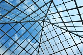
Despite appearances to the contrary, the curve of the roof is based on one simple shape that repeats over the whole area. This curve spans the building from front to back and is made up of two different radii. It starts off sharply curved, then straightens out to a gentler profile. This is because the roof has to bend sharply to blend into the facade. The main area of the roof maintains a flatter curve. To make life easier, the gutter defining where the facade ends and the roof begins is at the same height all around the building. However, the building is wider in front of each of the four cores, so the roof span is greater at this point. The roof is also higher over the cores. This creates a pleasing wavelike pattern – and works to the designer’s advantage. Imagine each arch that spans the roof being hinged at the gutter at the rear of the building. If an arch is lifted up at the front it will be higher than the adjacent arches. However, although the arch will still touch the rear gutter at the hingepoint, there will be a gap between the front gutter and the end of the arch. If that arch was made longer so that its curve continued, it would eventually hit the gutter-level at a point in front of the existing front gutter. The designers have simply moved the gutter forward to meet the end of the elongated arches, making the roof higher and wider around the cores. This solution means that the primary roof beams spanning the building all follow an identical profile, although they vary in length. Secondary steel beams run perpendicular to the primary members to provide bracing. Because the roof dips between the cores, the structure had to curve in another direction as well. To do this, secondary beams are set lower than the height of the primary members and a series of plates are welded to them, varying in height to follow the curvature of the roof. A section is attached to the top of the plates to define the direction of the curve. The roof cladding simply sits on the top of the perfectly curved steel structure.Downloads
Section through roof - How the geometry works
Other, Size 0 kb
Credits
Client Hutchison Whampoa Architect Foster and Partners Engineer Arup Contractor Exterior International Project manager CM International QS Davis Langdon & Everest








No comments yet