


Dennis has been the driving force behind the development which will become the new headquarters for around 950 of the Group’s employees. For the first time it will bring together under one roof design studios, laboratories, research and testing, as well as prototyping and production facilities for the company’s Formula One and high performance road cars.
The approach to the project has parallels with the way the company approaches grand prix racing. There has been the same search for perfection, evident in the smallest details – including the identical design for fixing screws whether they are holding together the facade or the furniture – through to the relationships that have been formed with the project partners. Collaboration has definitely been the name of the game and numerous bespoke products and solutions have been developed to meet the brief.
Design development
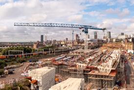
Finding a site for an industrial complex of this size is not easy. Location was vital, as employees would be relocating from 11 buildings in and around Woking. A 50 hectare parcel of land was found 5 km from the town in the surrounding green belt. Following a public enquiry planning approval was given although this came with a number of conditions. The biggest to influence the design was the limit on the building’s height – 11 m above ground level. The result is a low, deep-plan design, contained within a 20 000 m2 footprint – the extent of the farm buildings previously on the site.
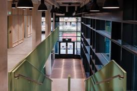
In plan the crescent form of the building’s main body is broken into seven, 18 m wide ‘fingers’, between which run double height streets designed to allow natural light into the building’s interior. These, along with the ‘boulevard’ running behind the lakeside facade, provide the primary circulation routes throughout. Housed in the basement and ground floor are the main production and storage facilities, with design studios, offices and meeting rooms located on the first floor.
Plant spaces and services were no exception when it came to client scrutiny. Initially German consultant Schmidt Reuter was brought in by McLaren to work alongside architects Foster and Partners in the concept design, taking it to tender stage. Amec successfully tendered for the job and as part of that agreement became responsible for the detail design and installation, with Schmidt Reuter retaining certain responsibilities including overseeing the commissioning. For the last 11 months it has also been fitting out the offices and the production areas, including the installation of the manufacturing equipment, and its facilities division will be maintaining the services after
completion.
Peter Kemm, regional director of Amec says the approach taken has been refreshing. The design team met on a weekly basis to discuss and approve the design and unravel any difficulties. “Nobody could build anything until it had been around the table and commented on,” says Kemm. “That was the strength of the job. There was no status of approval, other than the team’s decision to proceed.”
Schmidt Reuter borrowed heavily on German practices in the design of the building, though McLaren stipulated that only proven technology be used – it didn’t want to be used as guinea pigs for new technology, reasoning it had enough commercial risk tied up in its F1 cars. The German influence also filtered down into the procurement. “We were being introduced to other suppliers and manufacturers that we perhaps wouldn’t normally have come in contact with,” adds Kemm.
Cooling and ventilation
Environmental conditions within the building vary. The production spaces have fairly wide parameters generally above 16°C with an upper limit of 25-26°C. Each ‘finger’ is served by its own plant room positioned in the basement directly below the space, effectively creating an autonomous business unit. Fresh air is drawn in through two large (6 m x 1·5 m) concrete shafts that feed under the building and then split, coming up beneath the individual air handling plant. “This way air picks up the residual heat from the structure and the relatively low velocities reduces the frost protection that needs fitting to the coils,” says Alan Jones, controls and commissioning manager with Amec.
Displacement ventilation is employed in the ground floor production areas. Diffusers are built into the structural columns within the space – at around desk height – with supply air feeding in from below. The return air path is similarly incorporated into the structure by sealing one side of the ‘H-section’ column; this sealing plate ends just short of the false ceiling creating a void for pulling stale air out at high level and back down to the ahu.
Chilled ceilings are used in the offices and design studios where conditions are more tightly controlled – air temperatures typically range from 22°C to 27°C. Perhaps unusual for the UK the chilled ceilings are vaulted to match the arrangement in the production spaces on the floors below, where they provide better acoustic control. Similar arrangements had been installed in Germany, but Amec had extensive tests on full-scale mock-ups carried out by BSRIA to fully prove the system’s performance prior to installation. The ceilings are divided into 30 zones per floor; each equipped with a temperature sensor and a two-port control valve. Supply air is delivered via diffusers set in the raised floor and extracted above the ceiling void. The return air path is subtly incorporated into the junction where each run of curved panels meet on either side of the lightwells that run throughout the length of the top floor.
Three air changes per hour are provided for the offices and design studios, with this extract air being reused in the production facilities, in areas such as the paint shops and fume cupboards, to achieve the high velocity movement needed to purge any solvents. “We’re not looking for tight control in these areas,” says Jones. “But we are looking for lots of air movement to get rid of fumes and it seemed pointless to bring in cold air and start again.”
The extract passes via the heat recovery coils and out through the roof. Height restrictions have meant that the penthouse louvres are sunk below the roofline and incorporated into the shape of the riser.
The building is provided with 6 MW of installed cooling, with a further 1·5 MW for process cooling via four centrifugal and one absorption chiller – fed from the waste heat of the two 600 kW chp units which provide the building’s base load. One of the biggest loads is the wind tunnel (see box story) and this was the main driver for the creation of a 250 m3 chilled (6°C) water store. The store is sized to be able to provide 15 minutes of cooling to the wind tunnel and avoids the installation of a massive chiller farm. The five steel buffer vessels making up the store reach three-storeys in height and these have been incorporated as an architectural feature off the main boulevard.
The chilled water store has been further integrated with the fire strategy, ultimately saving on water storage for the sprinkler system. In the event of a fire the buffer vessels are isolated from the chilled water system through pneumatic valves. The two systems are capable of working independently while the sprinkler system is active.
The formal lake
The dramatic lake bordering the Technology Centre forms an integral part of the cooling infrastructure for the entire complex. The formal lake reaches around 2·5 m at its deepest point and together with the adjoining environmental lakes holds around 50 000 m3 of water. Water is pumped, one third directly from the lake and two thirds via a natural filtration system of reed beds and a cleansing biotope, through to a series of 300 kW plate heat exchangers which extract heat from the chiller plant. The water is recirculated via a 160 m long cascade that extends around the far edge of the lake. The form of the cascade helps to aerate the water, oxygenating the entire system, and dropping its temperature – the lake water is normally around 15°C. Overall, integrating the lake into the cooling strategy has reduced the requirement of cooling towers down from seven to two.
Rainwater from the curved roof is also collected to help maintain water levels during the year with any excesses passing into the adjacent environmental lakes, and further overspill discharging into the River Bourne.
Prefabrication
Dennis visited a number of factories owned by McLaren’s partners in both England and Germany to benchmark the contractors he intended to use for the Technology Centre. “There was no question that some of the systems used in Germany, the bracketing systems and lagging systems were ahead of the UK,” he says. This has led to the adoption of multi-services brackets being used throughout the building. Over 10 000 were prefabricated off the tender drawings with each one delivered to site in a single flat pack, complete with the necessary bracket, inserts, clips, fasteners and trays, on a just in time basis.
This cut down on both site storage and provided a neat uniform look. “We found it to be a very economical way of doing it,” says Amec’s Stephen Griggs, who admits to being slightly sceptical at first. “But when we put our first line of brackets down through the building we didn’t have to adjust a single one, we just laid the pipes on and it was there within 1-2 mm throughout the building.” Having mastered a typical installation it then became a straightforward process, which could be repeated throughout around 70% of the scheme.
The system was extended to the building’s 50 multi-service risers. These use dry-lined construction and led to a prefabricated self-supporting sub structure being developed which enabled the services to be installed independently from the other trades. The system worked well particularly as the only access to the basement, where 90% of the plant is installed, was via the two air intake tunnels which limited the size of prefabricated components.
Rather than using conventional ductwork in the basement air handling plant rooms Amec has employed a pre-lagged triple duct system. These 80 m runs, which provide supply and extract to the offices and production areas, are essentially ahu components brought in and bolted together to run alongside the ahus.
Victualic joints have been have used extensively on the chilled and hot water services pipework throughout the project. These were specifically manufactured to suit the curvature of the basement services corridor – a straight 6 m length of pipe is connected to a faceted Victualic. They have also been used to compensate for any expansion and contraction, including the movement of the basement box which is expected to vary by about 70 mm throughout the year.
Amec also worked alongside McLaren’s own designers to develop the compact multi service outlet panels installed at each workstation in the manufacturing and assembly area. These allow power sockets, compressed air lines hydraulic lift controls, and computer outlets to be accommodated within a panel measuring less than 600 mm by 300 mm, helping to maintain the clean lines of the building.
The Technology Centre is unique in many ways, in the activities it houses, its sheer scale and the standard of finishes used. But what sets it apart as a building project is probably the client. It’s unusual for any design team to work for someone who participates as strongly as they have done in the design process, and in particular one who makes and designs things to a far higher standard than the construction industry normally achieves. For evidence of what such a collaboration can achieve, just look at the building.
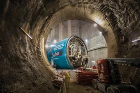
Tunnel vision
The aerodynamic performance of an F1 car is a decisive factor when it comes to winning races. This is why at the heart of the Technology Centre sits a 145 m long wind tunnel capable of accommodating 1:2 scale car models. Sitting in the basement, it was the first part of the development to be brought on line and its services were maintained in operational condition throughout the entire construction programme. The building is an acoustically sealed block with two walls linked to the structure by rubber mounts to minimise noise breakout and vibration.The wind tunnel reproduces the conditions the car is subjected to as it travels along the surface of the track using a 4 m diameter fan that is capable of moving air at a rate of 15 m3/s. Each operation of the fan develops 1500 kW of excess heat along with further heat generated by the friction of the air against the sides of the tunnel. This heat would inevitably lead to the density of the air changing with the knock on effect that the readings of the test would vary. These cannot be accurately calculated out, so instead it is necessary to keep the huge mass of air at a constant temperature. This is achieved by circulating 6000 litres of chilled water per minute through a 9 tonne coil installed in the tunnel.
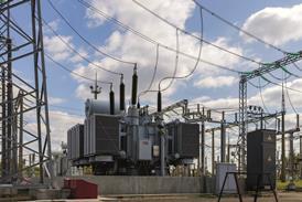
In addition to the control and switchgear it was necessary for Amec to install a dedicated hv transformer for the operation of the wind tunnel fan. On start up the fan draws over 1 MW of electricity and requires the local power supplier to be notified so that they can compensate for the surge.
Source
Building Sustainable Design
Postscript
The building is equipped with an L2 fire protection system, with L1 enhancements, and includes over 10 000 sprinkler heads.

No comments yet