This CPD, sponsored by Siderise, outlines developments in cladding used in high-rise residential tower blocks and examines the testing involved prior to installation

CPD CREDITS: 60 MINUTES
DEADLINE: 11 OCTOBER 2019
For more information about Assemble Media Group’s CPD distance-learning programme, click here

Introduction
The materials and products used in cladding high-rise residential developments continue to be put under scrutiny, along with the testing regimes such products undergo. This CPD will outline developments in the products used in high-rise residential tower blocks and examine the testing involved prior to installation.
Considering risk
By the nature of their construction and the materials used, all buildings carry a degree of fire risk. Clearly, the aim is to keep such risk as low as possible but the implications for occupant safety can be affected by a range of factors. Building rules and regulations are designed to control these. The type of cladding used is a crucial consideration – it is generally designed to provide the intended aesthetic, prevent water ingress and mould accumulation, aid insulation and inhibit fire.
From the cavity barrier manufacturer’s point of view, the basic definition of a rainscreen ventilated facade is an assembly comprising an outer panel, a ventilated cavity and an inner leaf.
The advantages of this arrangement are:
- Penetrating water is drained
- It allows ingress of air at the base and egress of air at the top
- It circulates air to expel moisture
- Allows ventilation
- Pressure can be equalised
- It prevents a “chimney effect” through cavity barriers.
The majority of water is deflected off the face of the facade, with any penetrating water being disposed of through drainage. The use of cavity barriers in rainscreen ventilated facades fixed to the outside of a building is designed to prevent a “chimney effect” within the cavity. This needs to be effectively compartmented in order to prevent unchecked fire spread within the cavity.
Two examples are worth considering. The Polat Tower in Istanbul is a 42-storey skyscraper comprising 400 luxury apartments, which was constructed partially from curtain walling and partially from ventilated rainscreen cladding. In 2012, a fire started in air conditioning units – there were no cavity barriers in the ventilated section of the facade – and swept up through the facade, the aforementioned chimney effect. The blaze was blocked by the vertical barriers in place for the curtain wall section of the facade and there were no casualties.
The Polat fire demonstrates the need for ventilated cavities to be effectively closed in the event of a fire. Effective compartmentation requires horizontal cavities, even on sheer walls.
At Gloucestershire County Cricket Ground’s apartment scheme, which had 30 different types of facade, this was addressed at the design stage. Consideration had to be given to each facade type, not only from the fire perspective but from the need to prevent water ingress and mould growth.
Siderise worked with the designers to change a standard “one-size-fits-all” approach to selection of cavity barrier product suitable for each type, thus avoiding unnecessary fire compartmentation issues and associated risks.
Facade design
While facade design has matured to produce increasingly sophisticated and complex designs comprising different materials with varying properties, in combination with different methods of support systems and installation, in terms of
fire compartmentation they are covered by the same regulation.
In England and Wales, Approved Document B (AD B) offers guidance on ways to satisfy the Building Regulations and relevant performance requirements. In Scotland, reference is made to the Technical Handbook, Section 2, while in Northern Ireland it is Technical Booklet E.
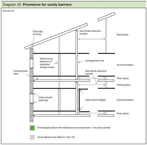
Regarding the application of AD B Volume 2, the provision for cavity barriers is illustrated in the diagram above. Contrast here the internal cavity, where a firestop is required to be installed in order to maintain continuity of fire resistance of the compartment element; this is the case when a perimeter barrier firestop is installed between a slab edge and the interface with curtain walling. In terms of the context of rainscreens, the specifier is more concerned with the subdivision of the external cavity. Any building with a compartment floor above the ground floor needs to have cavity barriers in an external cavity. Use is independent of a building’s height and/or its designated use.
From the images opposite, cavity barriers can be seen as required at compartment floors, alongside those to close around openings, whether windows or doors.
In terms of AD B, the most simple definition of a cavity barrier would be a construction designed to close a concealed space against penetration or spread of smoke or flame. When it comes to functional performance, Buildings Regulations state specific performance requirements in terms of integrity and insulation criteria. In England, Wales and Northern Ireland, a cavity barrier is required to provide 30 minutes’ integrity and 15 minutes of insulation, while there is no requirement for insulation in Scotland.
Building Regulations also requires cavity barriers be tested to meet that performance. AD B states that “the product should be in accordance with a specification or design which has been shown by test to be capable of meeting that performance; or have been assessed from test evidence against appropriate standards”.
Additionally, fire engineered and insurance-driven specifications increasingly require an EI30 – performance classification of 30 minutes performance for both integrity and insulation.
CWCT performance standards
In parallel with the Building Regulations, reference also needs to be made to the Centre for Window and Cladding Technology’s (CWCT) performance standards, which provide a framework for specifying building envelopes.
Indeed, National Building Specification (NBS) and National House Building Council (NHBC) standards are based on the CWCT’s “Standard for systemised building envelopes”. This states that for cavities in rainscreen walls, barriers shall be provided:
- On the line of any compartment wall or floor
- To close the cavity around penetrations through the rainscreen for windows and doors
- To subdivide the cavity with horizontal and vertical barriers.
AD B rules on cavity barriers
In terms of the positioning of cavity barriers for rainscreen walls, AD B states that cavity barriers are to be provided:
- At the junction of the wall with a compartment wall or floor
- To close the edges of cavities including around window openings
- To limit the maximum dimension of the cavity to 20m where the surfaces of the cavity are Class 0 or 1m and 10m in other cases, including sheer walls.
NHBC design guides on the positioning of cavity barriers
- Horizontal cavity barriers provided at each floor level
- Vertical barriers at centres not exceeding 6m
- Vertical cavity closers at centres not exceeding 1.5m within 6m of an internal or external corner
- A vertical closer as close as possible to an external corner, normally within 300mm.
The design guide says this compartmentation is in addition to the requirements of Building Regulations for cavity barriers to control the spread of fire and smoke. However, the same barriers may be used.
Approach to product design
So how do manufacturers factor all of this into a product design approach, where form is determined by function? And with regard to ventilated facades, how are the basic needs of rainscreens – the requirement for ventilation and drainage – bridged with the need to seal the cavity to prevent the spread of smoke and fire?
Such functional requirements present a practical and safety paradox in that conventional “full width” seals will prevent ventilation and drainage but with consequential issues in terms of moisture ingress and damage.
The accepted market solution (as acknowledged by the CWCT standard) is that the conflict between the needs for ventilation and fire sealing can be overcome by the use of intumescent materials. These will allow the cavity to be maintained under normal circumstances but seal the cavity in the event of a fire.
Cavity barrier at a compartment floor (above) and cavity barrier to close around openings (below)
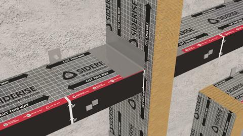
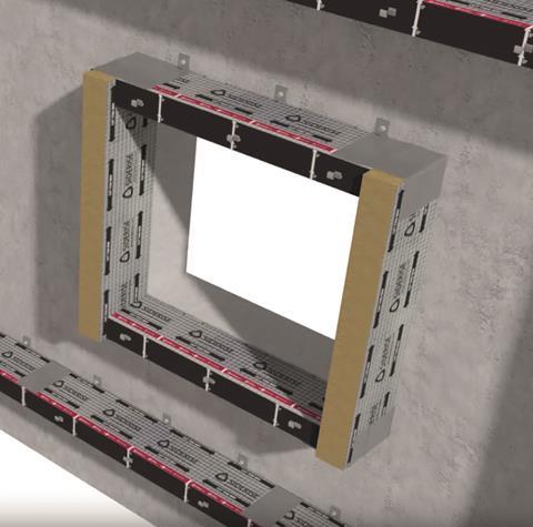
The premise is that the barriers are sized and installed to maintain the desired ventilation air gap. In the event of a fire, the intumescent will activate at a critical temperature, typically around 130°C, and begin to expand. For an initial period, smoke will bypass the cavity barrier until the intumescent seal is fully closed. The “integrity” criterion is re-established after the initial closure. The expansion continues to fully close the void.
For guidance in terms of required air gap size, many manufacturers refer to the CWCT standard. The standard says in terms of air, water and wind resistance, there are “different joint and cavity combinations” for rainscreens. For sealed and closed joints, the air gap must be a minimum of 25mm drained and ventilated; for labyrinth and baffled joints, the air gap must be a minimum 38mm drained and ventilated or pressure equalised, and for open joints, there must be a minimum air gap of 50mm, pressure equalised only. Additionally, the standard states that the “area of the path shall not be reduced by more than 50% at fire barriers or support rails”.
When considering the reduced gap at fire barriers, this equates to a minimum 12.5mm for sealed and closed joints, a 19mm minimum gap for labyrinth and baffled joints and a 25mm minimum gap for open joints.
As regards testing, different scale fire tests are used for different applications. They range from small-scale to large. Small-scale tests on linear joint seals and open state cavity barriers must comply with BS 476-20, EN 1366-4 and Association For Specialist Fire Protection (ASFP) technical guidance document 19.
For medium-scale testing on perimeter barrier firestops and protected spandrel systems (curtain walling), the compliance must be with EN 1364. For cladding assemblies, large-scale system tests are undertaken to BS 8414-1/2 and the tested system classified to BR 135.
Testing for rainscreen cavity barriers
Siderise first began to test cavity barriers for rainscreen in the late 1990s – prior to that, only assessments were available. The ad hoc B 476-20 barrier tests were conducted with the barrier fixed in a cavity between walls of fire-resisting construction.
The regime involves the standard time/temperature curve at standard pressure – but the barrier is installed to maintain a 25mm or 50mm gap. Under test, the intumescent reacts to increasing temperature. Key criteria are the activation time and ability for the intumescent to close the cavity as quickly as possible. Not all intumescent materials are the same. They typically react in varying ways at different temperatures and pressures.
For standard proprietary intumescent, when the temperature rises there may be a significant time delay before they expand to adequately form a seal. Activation time and expansion properties are critical to performance of the seal. The faster the time to close,the better.
Testing for ‘open state’ cavity barriers
Performances between competing products are inevitably different and not all are ultimately fit for purpose. In 2014, the ASFP responded to the need to be able to classify the performance of products with the publication of a technical guidance document specifically for the testing of “open state” cavity barriers.
This provided a new formal definition for open state cavity barriers, which are cavity barriers that allow for ventilation and drainage in the cold state, but either close in a fire or are inherently fire-resisting, providing fire separation in the cavity.
And from the ASFP technical guidance document emerged a standard performance for effective closure. This lays out an effective closure of the open state cavity barrier and requires that the time taken for the cavity barrier to close shall be measured and recorded. Cavity barriers must close within five minutes from the start of the test or they are deemed to have failed.
Activation time and expansion properties are critical to the performance of the seal, with the “time to closure” paramount. Some companies, such as Siderise, wanted a much faster closure limit since it believed this was possible undertest conditions.
The ASFP technical guidance document also outlines the test configurations and failure criteria. It is based on the existing linear joint seal test, but modified with upstands to better replicate the cavity construction.
Third-party certification
Performance to the ASFP technical guidance document 19 can now be verified by third-party certification, which is essential to ensure that the specifier and end user are provided with a suitably tested, audited and repeatable product or system solution.
Procurement
When selecting a cavity barrier product, contractors need to be aware of a number of key requirements.
Products must:
- Meet integrity and insulation rating
- Maintain air gap horizontally to back of panel
- Close gap within five minutes
- Provide full closure (with compression) vertically
- Must provide means of positive retention to back wall
- Should have continuous strip of intumescent on leading edge
- Should take consideration of design life of the building.
Considerations to go alongside these key features:
- Select from system range; match EI performance requirement; ensure that compatible horizontal and vertical barriers are available from the same supplier
- In accordance with the cladding system joint type and design, select maximum air gap size – system range includes options for 25mm and 50mm air gaps
- Test report – ask to see the data
- Third-party approval – ask to see the certificate
- Consider seal closure time – faster is better
- Fit to maintain integrity – without panel registration; check ability of the cavity barrier to maintain serviceability movement
- Use non-combustible fixings appropriate to substrate
- Pay attention to the detail to corners; detail to T bars, intumescent material to sit in front
- Cassette panel arrangements may require specific considerations to accommodate wider gaps
- If deemed a moist zone; choice of fixing brackets, stainless steel recommended; durability of intumescent and barrier system.
System testing
Wherever possible refer to system test evidence for the specific cladding assembly being considered.
During the last 18 months the market in the UK and overseas has undertaken a significant number of large-scale cladding tests – most notably to BS 8414-1 and BS 8414-2. The systems are subsequently classified to BR 135.
In all cases, please make direct contact with the test sponsor for details of the tested assembly, design, system performance and classification.
Installation
Many companies take the view that the cavity barrier is to be installed with interrupted thermal insulation above and below. Insulations may be “fire safe”, but not tested to the specific requirements of a cavity barrier. To do otherwise introduces questions of integrity performance – either due to the properties of the thermal insulation material, gaps at joints or uneven surfaces.
Material should be cut to allow compression to the back of the panel and brackets should be impaled into the barrier. By convention, the vertical barriers need to be installed first. Brackets should be fixed to the wall and tape foiled to joints.
At an internal corner, horizontal barriers should be carefully cut to form a simple mitre, tightly abutted, ensuring continuity of the coverage of intumescent, with joints foil taped. Similarly, there is a simple treatment at an external corner; vertical barriers are installed first at full cavity width for compartmentation. Horizontal barriers are installed with tight abutted intersection and joints are also foil taped.
At an intersection, vertical barriers are installed first at full cavity width for compartmentation. Horizontal barriers are installed with tight abutted intersection. Joints are foil taped. For windows, extend vertical barriers above and below window apertures. Set horizontal barriers tightly abutted between vertical barriers. Seal joints with foil tape.
This procedure is similar for doorways.
In parallel with Building Regulations, also refer to CWCT performance standards as these provide a framework for specifying building envelopes.

How to take this module
Assemble Media Group’s CPD distance-learning programme is open to anyone seeking to develop their knowledge and skills. Each module also offers members of professional institutions an opportunity to earn between 30 and 90 minutes of credits towards their annual CPD requirement.
This article is accredited by the CPD Certification Service. To earn CPD credits, read the article and then click the link below to complete your details and answer the questions. You will receive your results instantly, and if all the questions are correctly answered, you will be able to download your CPD certificate straight away.
CPD CREDITS: 60 MINUTES
DEADLINE: 11 OCTOBER 2019
Privacy policy
Information you supply to Assemble Media Group Limited may be used for publication and also to provide you with information about our products or services in the form of direct marketing by email, telephone, fax or post. Information may also be made available to third parties. Assemble Media Group Limited may send updates about Building CPD and other relevant Assemble Media Group Limited products and services. By providing your email address you consent to being contact by email, telephone, fax or post by Assemble Media Group Limited or other third parties. If at any time you no longer wish to receive anything from Assemble Media Group Limited or to have your data made available to third parties, contact the Data Protection Coordinator at building@building.co.uk. View our full privacy policy here




No comments yet