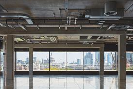
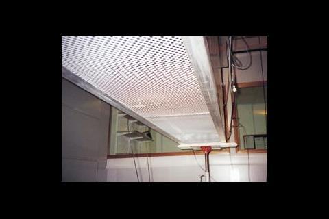
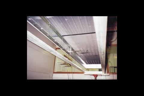
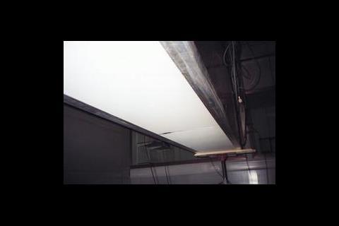
This was the very problem faced by the services consultant WSP South. The services designers had specified a passive comfort cooling system for a new British Telecom office building, and an adjacent office for the DETR at Temple Quay in Bristol. In both instances, the system comprised chilled beams suspended above a perforated metal ceiling.
When WSP engineers were selecting the chilled beams, opinions conflicted on the effects of different sized free areas and perforations in the suspended ceiling. While it was generally agreed that free area had an influence, the relationship between beam cooling output and hole size needed to be clarified.
In discussion with Waterloo Air Management it was decided to carry out a test using a selection of SAS ceiling tiles which were being considered for both projects.
In an earlier test for British Telecom, smoke traces showed that the free area for the perforated facing beneath a void-mounted chilled beam could influence the cooling capability of the system. It also affected the resulting room airflow regime.
Although close-coupling the beam to the facing with side skirts could help to maximise the output, it was unclear how much reduction in cooling capacity would occur when reducing the free area from the ideal of 50%.
WSP South and Waterloo decided to carry out more tests, this time on a purpose-designed test rig.
The test rig
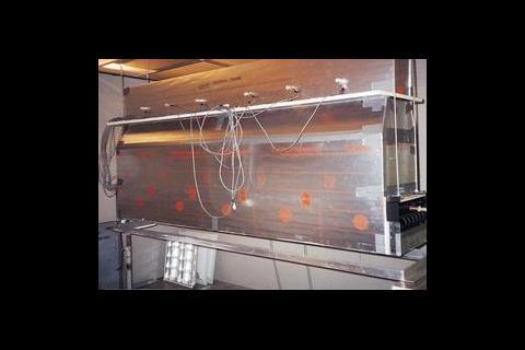
An insulated cowling was constructed around a 2.5 m long, 0.4 m wide, three-row chilled beam. The rig was constructed so that a sealed air circuit was formed through the finned area of the beam.
The upper part of the cowl was tapered to form a ducted air inlet. Six air velocity probes were then installed. The lower section was fitted with a lower tray, 100 mm below the beam, to take the ceiling tile samples.
Temperature controlled chilled water was supplied to the beam via a flow monitoring station. The flow and return water temperatures were measured and relayed to a data logging system, together with the induced and discharge air temperatures.
The entire rig was run for around one hour so that all surfaces, water supply and room air temperatures reached a stable condition.
Test results
For each set of logged results, a number of comparable test conditions were selected as a basis for the calculation of the cooling capacity.
Examination of the test results revealed a progressive fall off in the cooling capacity of the beam as the free area of the perforated face material is reduced below approximately 50%. Comparisons of the results for the 50% free area with the control condition would suggest that the material has a negligible influence on the cooling capacity of through flow of air, although the discharge air temperature reduced by around 1.50C.
As the free area is reduced further to 39%, the cooling output is reduced by around 6%, although the through flow and discharge temperature appear to be unaffected.
The fall off in output becomes more noticeable below this, reducing by 24% at 25% free area, and 30% at 22% free area. In the latter case, where two hole sizes were tested for the 22% free area material, it is evident that the smaller holes of the SAS 1522 ceiling tile (1.5 mm hole, 22% perforation) further reduced the output by 40%.
Similarly, it was noticeable that the 25% and 22% materials produced a substantial reduction in the through flow of air – up to 54% in the case of the SAS 1522 tile.
Correspondingly the restriction imposed by the lower free area also reduces the discharge air temperature by around 10C when compared with the 50% free area material.
While it could not be proven on test, it is possible that the combination of reduced airflow rate and temperature experienced at these low free areas could also influence the characteristic of the air plume. This could have caused it to destabilise the flow regime within the occupied zone.
In the extreme case it seems likely that this would give rise to the so-called 'pumping phenomenon'. This means that pools of chilled air collect above the perforated facing, and which then break through in isolated pockets when the mass is great enough to displace the room air beneath the ceiling.
It is also worth noting that these lower free areas, particularly with hole sizes of 2.5 mm or less, will be more prone to collect air contaminants. Ultimately, this could lead to the ventilation airflow being even more restricted, and it could also affect the cooling output of the beams.
Test conclusions
Although the tests were conducted under laboratory conditions, and despite being based on a set of ceiling samples provided by SAS, on a purely comparative basis they do identify some useful design pointers.
Facing materials of 50% or more free area, with 10 mm diameter holes, produce no measurable reductions in the output of a chilled beam. Reducing the area to 40%, with holes of 4 mm diameter, will reduce the output by around 6%.
In the author's opinion, there is probably little merit to be had in fitting side skirts to beams where the free area of the facing falls within this range. However, side skirts should always be fitted where the free area of the facing is 35% or less.
Where architectural requirements call for high obscurity, the free area of the facing material should be no less than 25%, with a minimum hole size of 3 mm.
No matter what the amount of free area, ceiling grid hole sizes that are less than 2.5 mm in diameter are not recommended.
Downloads
Figure 1
Other, Size 0 kb
Source
Building Sustainable Design
Postscript
Neville Rye is an associate director with consulting engineers WSP South.


