Unfortunately for the University, its chosen site was fairly compact, noisy and enclosed – hardly an ideal location for a building likely to suffer from high cooling loads generated by equipment and IT provision. It was evident that the size of the site would force a deep-plan approach, and that noise from the nearby elevated roads would not allow reliance on opening windows for ventilation.
The late Professor Neil Bowman and his partner Peter Reeve were selected to investigate natural ventilation for these difficult conditions, and won the m&e engineering commission. Computer modelling was contracted to De Montfort University's Institute for Energy and Sustainable Development (of which Bowman was then Director and which is now headed by Professor Kevin Lomas). This team had previously worked with the appointed architect, Alan Short, on De Montfort's innovative naturally ventilated Queens Building.1
Various building configurations were investigated. Eventually, a highly heat-efficient 50 m square plan was selected for the 9000 m2 building, with vertical wells punched through for natural light and air supply and removal, supplemented by perimeter ventilation stacks. This still left a lot to do as this building is billed as the biggest naturally ventilated building of its type in the world.
The building has not compromised its objectives with contingencies: in the main floors above ground there is no cooling and no mechanical ventilation, other than a small ground floor print-room area.
Natural ventilation strategy
The building has four floors above ground on a square plan. Under the ground floor there is a 2 m air supply plenum level and a partial basement level below this. On the top floor, the occupied area is pulled in from the corners to inside the lightwells, making a cruciform floor plan.
Construction is of brick finish with double-glazed argon-filled windows to a U-value of 2.0 and a warm roof with 200 mm of insulation. Room height is 4 m to the exposed concrete ceiling. Structural steel beams of 1 m depth extend down from the ceiling, but these have circular holes which allow virtually free airflow at ceiling level.
Three sets of vertical wells or stacks provide for air supply and exhaust. Four corner lightwells provide tempered air supply to all floors – these wells are inboard by 7m from the perimeter of the building. A single central lightwell provides an exhaust air path from the centre floor areas, while twenty ventilation exhaust stacks take air from the perimeter. These are supplemented by four further stacks for the top floor.
The lightwells are classified as such, and not as atriums, and fire requirements have been met by providing smoke-venting through these elements.
For normal ventilation, air enters the under-floor plenum from the perimeter and passes into the base of the corner lightwells. Moving up the corner lightwells the air is tempered by a full-area horizontal heater battery. Low-level dampers on each floor control the flow of air into rooms from the supply lightwell. From there the air passes over trench convective heaters. Warm air collects at high level, moving around the room through the penetrations in ceiling beams, and then out of the room via high-level dampers into either the perimeter stacks or the central lightwell.
The central lightwell has a glazed horizontal base extending 1.3 m below the ground floor ceiling to provide natural light and allow space for high level extract dampers from the ground floor. This lightwell increases from 6 m square plan at ground floor level to 9 m at third floor level. It has a glazed top to a height of 6 m above the roof.
Window vents on all faces are controlled by motorised actuators, while motorised blinds prevent unwanted sun penetration. The window vents are reported to be controlled according to wind direction to ensure that wind assists with negative pressure requirements.
The corner lightwells are of 6 m square section and have a single-row finned tube heat exchanger at ground level. The lightwells extend up to just above the third (top) storey floor level to allow low level supply dampers at that level. The corner lightwells have glazed roofs with actuated window vents to allow venting in hot weather.
The 3 m square brick perimeter stacks extend upwards from external ground level to 6 m above roof level, where they have custom designed aluminium terminations. They pick up used air from high level dampers on each floor - including basement level in some cases. The terminals have been wind tunnel tested at the University of Wales, Cardiff. They are reported to ensure that wind provides a net extracting effect in all conditions. Their appearance was changed somewhat by a late addition of structural horizontal bars to reduce the chance of the aluminium fairing falling off.
Building services systems
Highly efficiency (non-condensing) Stokvis Econoflame boilers provide heating to three systems:
- air in the four lightwells, which is pre-heated to around 150C
- trench heating of air as it enters room from the supply lightwells
- perimeter heating (mainly radiators, centrally controlled)
A 210 kW chp system by Nedalo serves the local heat load and the neighbouring William Morris building. It can also feed electricity back into the University's electricity main. This installation follows good experience with earlier Nedalo chp packages. These were provided under a supplier-financed deal and later purchased outright by the University to obtain increased savings.
A central chiller provides cooling mainly for the adjacent School of the Built Environment but it also serves the library's 24 h access basement computer room for students, and a small server room. The ground floor print-room area has a local mechanical ventilation system but no cooling.
Lighting of the general areas is by suspended T5 fluorescent fittings giving substantial uplighting as well as downlighting. Lights are controlled by a fully addressable Luxmate central control package which makes use of presence and light detectors on each set of luminaires. Lights are dimmed automatically to make use of the extensive daylighting. At the time of the visit the dimming appeared to be working effectively.
Design details
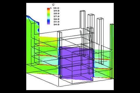
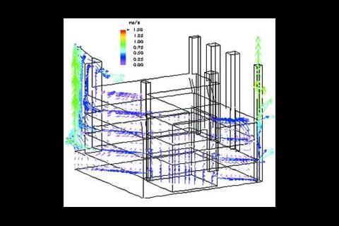
Damper sizes increase as you go up the building, as the stack-induced head reduces. Dedicated stacks are needed for the third floor as the computational fluid dynamics simulations showed that air might spill back into the room from the central well instead of being extracted. However the perimeter exhaust stack are still used.
Night ventilation operates by opening room air dampers if room temperatures rise above 220C.
The overall stack head available of 4 Pa (see box, 'Flowing naturally') demanded considerable effort to limit pressure drops in the airflow path from inlet via plenum. Measures to limit this include:
- no-loss supply plenum and supply lightwells, and exhaust lightwell and passive stacks.
- single row horizontal heat exchanger in the base of the supply lightwell
- large damper areas with low pressure-loss dampers
- pressed damper steel grills with high (90%) free area
- an increase in damper sizes on higher floors
- secondary heating of air as it enters the room is by convective trench emitters with no pressure drop. These include an induced-airflow loop to ensure that the desired air temperature is measured for control purposes
Although air in the four supply lightwells is tempered/preheated to typically 150C in winter, thereby reducing the effect of any leaks, particular care has been taken with the large areas of dampers to ensure that they provided adequate sealing. Dampers were selected with neoprene sealing strips and spring-loaded side seals, and successively developed with the supplier through six versions, with testing on-site and accelerated wear.
While the accommodation is mostly open-plan, there are separated rooms for teaching and administration which require ventilation. Mostly these rooms are located between the "corner" lightwells and the perimeter – so supply and removal of air does not pose any problems. Where rooms are not adjacent to the corner lightwells, air is provided directly from the open plan areas via transfer grilles. For acoustically more sensitive areas, the transfer air is made to pass along the partition space for around two meters: the space has a depth of around 500 mm and is lined with absorbent material.
Overall assessment
The University's project manager for the development reports very positive feedback for the building to date, with far fewer problems raised by occupants than expected. Also his personal experience is that the building has an airy environment compared to conventional naturally ventilated offices. At the time of the visit this view was supported as the building had a pleasant fresh feel.
So far it looks promising that the building can keep cool in summer and the compact shape bodes well for keeping warm in winter, with low heating costs. However the building has required some radical thinking and will provide interesting answers to a number of questions.
Can the building's various control modes be managed effectively and easily? This is where a number of advanced natural ventilation buildings have tripped up, but there is no indication yet that it will be a problem here. If this is a problem then there will either be lack of comfort or extensive operational time, or operation in a mode or with extra hardware not intended by the designers.
Will the building be "maintenance free"? If the building keeps cool and can be managed effectively, then this question reduces to maintenance of the unusual aspects of the fabric and plant, such as the stack superstructures, vents and dampers, blinds, and the extensive ventilation paths. Will these need extensive cleaning or maintenance repair? Will the lightwell heat exchanger get dirty quickly? Another interesting question is how well the arrangements for internal separated rooms work in terms of air flow quantity, quality and attenuation2.
What about the array of ventilation stacks? They look interesting and they make a potentially valuable marketing statement about the building. But they must add to costs, which raises the question: can the concept be made to work without them? In conclusion, if this building is successful it will open a market for larger, deep-plan, naturally ventilated buildings. The commitment of the designers to achieving this is evident from the design and therefore one hopes that the building will live up to its potential.
Downloads
A section showing the central lightwell and perimeter exhaust stacks.
Other, Size 0 kbFirst floor plan showing the three types of ventilation well.
Other, Size 0 kb
Source
Building Sustainable Design
Reference
1Bunn R Greatorex T & Stevens B, `Learning curve', Building Services Journal, 10/93. 2Ashbridge R & Cohen R, PROBE 4: Queens Building, Building Services Journal, 4/96.
Postscript
John Field MA is director of Target Energy Services, www.targ.demon.co.uk







No comments yet